background image

13

Operation

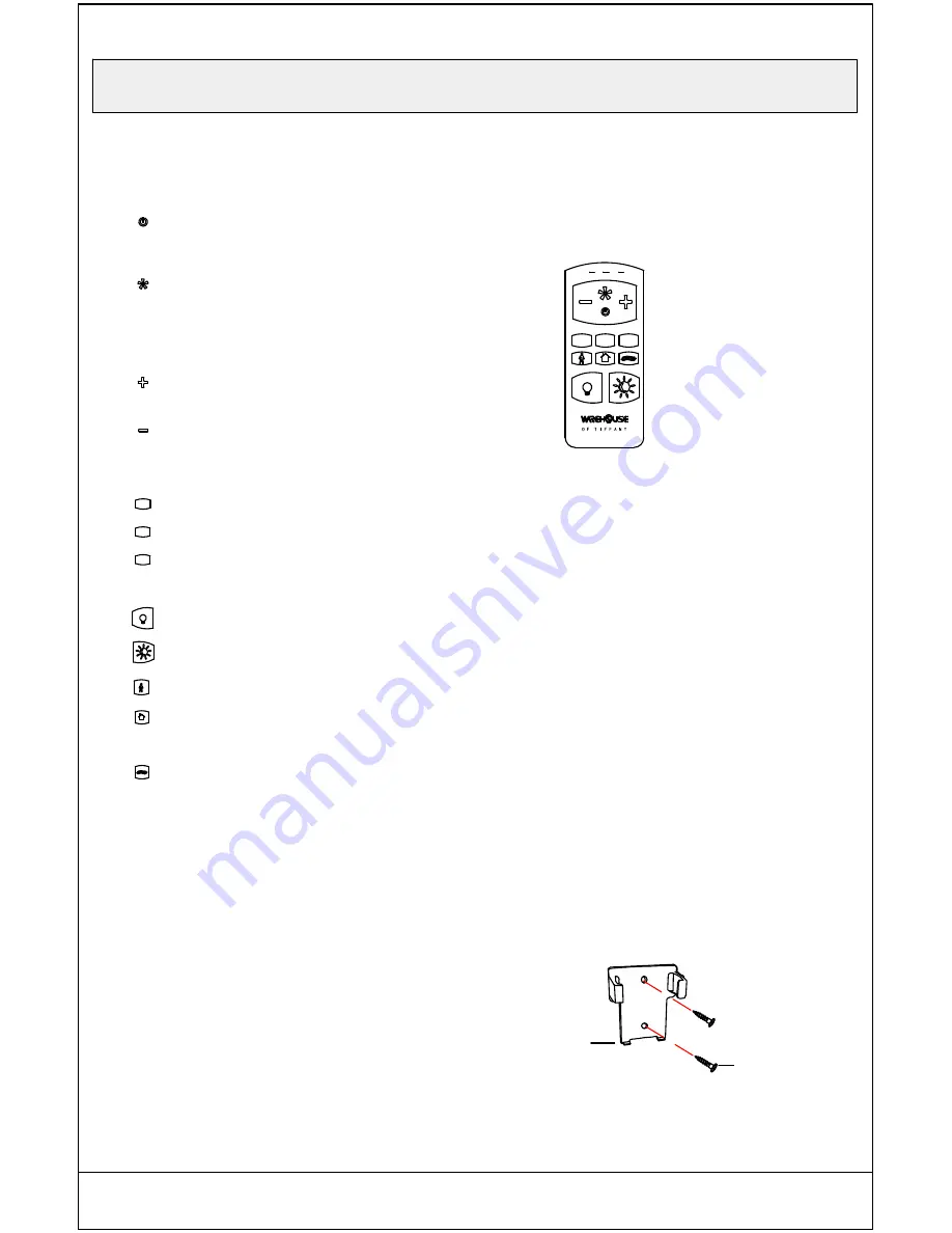
REMOTE CONTROL OPERATING INSTRUCTIONS

Auto off after 2 hours

1.Fan function

         Press and release the button to tum the
          fan on or off.

         Fan off. The fan memory function will
         store the current setting for the next
         time the fan is in use.

2.Speed functions


Press+ to increase the desired speed of

          the fan from low, medium, high.

          Press - to decrease the desired speed of
          the fan from high, medium, low.

3.Timer functions

4.Light functions

Pres and release button one time will turn the light on

Press and release button one time will turn the light off

M

II

□ Remove two remote control holder plugs from the
remote control holder (I). Note that the plugs have unique

tabs that allow them to fit only in one hole.

INSTALLING THE REMOTE CONTROL HOLDER

2hr

4hr

8hr

2hr

4hr

8hr

Auto off after 4 hours

Auto off after 8 hours

Walk away delay Turns light off after 60 seconds.

Safe Home Randomly turns the fan's light on and off to

 simulate use while away from home. Make it look like
 someone's home while you are away.

Nature Breeze Randomly cycles the fan speeds to

simulate naturally occurring air movement.

□ Attach the remote control holder (I) with the tew remote
control holder mounting screws (II).

Summary of Contents for AL01P01

Page 1: ...USE AND CARE GUIDE SI 52 INCH CEILING FAN IC AS MG AL01P01 ...

Page 2: ... Table of Contents 2 Safety Information 3 Warranty 4 Pre Installation 4 Operation 13 14 Care and Cleaning 14 Assembly 8 Assembly Hanging the fan 9 10 11 12 Pre Installation continued 5 6 Installation 7 Troubleshooting 15 ...

Page 3: ...ith the limits for a Class B digital devico pursuant to Part 15 of the FCC Rules These limits are designed to provide reasonable protection against harmful interference in a residential installation This equipment generates uses and can radiate radio frequency energy and if not installed and used in accordance with the instructions may cause harmful interference to radio communications However the...

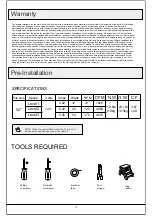
Page 4: ...ing any accessories is not covered by this warranty Because of varying climatic conditions this warranty does not cover any changes in brass finish including rusting pitting corroding tarnishing or peeling Brass finishes of this type give their longest useful life when protected from varying weather conditions A certain amount of wobble is normal and should not be considered a defect Servicing per...

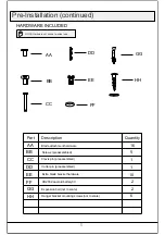
Page 5: ...FF GG HH AA BB CC DD GG Part Description Quantity 16 1 1 10 2 2 Clevis pin preassembled Cotter pin preassembled Screws preassembled 5 6 5 FF EE HH Blade attachment hardware Extra blade bracket hardware CR2032 aneroid battery3V Expansion bolt not to scale Hanger bracket mounting screws not to scale 3V ...

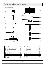
Page 6: ...all downrod assembly Coupling cover Part Description Quantity Remote control holder Remote control SG A10 H L M N O 1 1 5 1 1 1 Blade bracket flange screws pre installed Blade Toughened glass Fan motor assembly Light kit 2hr Metal tapping washer Finial Pre Installation continued G H I J K L M N O Coupling ring preassembled Receiver 4hr 8hr ...

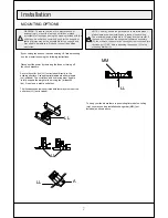
Page 7: ...he decorative canopy bottom cover and turn the canopy C 180 before attaching the canopy C to the mounting bracket A If your ceiling fan does not have an existing UL listed mounting box then install one using the following instructions Disconnect the power by removing the fuses or turning off the circuit breakers Secure the outlet box LL not included directly to the building structure Use appropria...

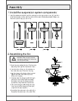
Page 8: ...res exiting the top of the fan motor assembly F through the downrod as shown 2 Loosen but do not remove the setscrew on the collar P on top of the motor housing 3 Align the holes at the bottom of the downrod B with the holes in the collar P on top of the motor housing 4 Carefully insert the hanger pin CC through the holes in the collar P and downrod B Be careful not to jam the hanger pin CC agains...

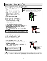
Page 9: ...rk the spots where the 4 Self Tapping Screws Il will be drilled 2 Remove the Mounting Bracket A dril 4 holes for 3MM diameter instal the mounting bracket onto wooden ceiling with the 4 Self Tapping Screws II Washers IMPORTANT SCREWS MUST BE TIGHTENED TILL SNUG For concrete ceiling use the percussion bit with diameter 6mm to dill holes according to the length of expansion screws Then use the attach...

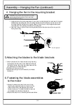
Page 10: ...rt the receiver K into the mounting bracket A with the flat side of the receiver K facing the ceiling 5 Attaching the blades to the blade brackets 1 Attach a blade H to a blade bracket I by inserting screws AA into the holes in the blade and through the blade bracket Note that the rubber washers are pre attached to the blade bracket 2 Tighten each screw securely 3 Repeat these steps for each blade...

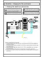
Page 11: ... the remote control for proper signal transmission between the remote control and the fan s receiving unit Yellow Green Neutral Wire for Fan Live Wire for fan Live Wire for Lamp Control Yellow Green Terminal blocks Ground wire Ground wire Antennd wire L N Motor to receiver electrical connections 1 Connect the fan wire with receiver wire by connect terminal Receiver to house supply wires electrical...

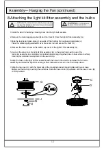
Page 12: ...tor plugs together blue to blue white to white Carefully tuck all wires and splices into the switch cup 6 Align the holes in the light kit fitter assembly with the holes in the switch cup below the fan motor assembly and install the light kit mounting screws that were removed in the fourth step above 7 Align the top cover C with the hole knob of the mounting bracket A and tighten with two screws M...

Page 13: ... Press and release button one time will turn the light off M II Remove two remote control holder plugs from the remote control holder I Note that the plugs have unique tabs that allow them to fit only in one hole INSTALLING THE REMOTE CONTROL HOLDER 2hr 4hr 8hr 2hr 4hr 8hr Auto off after 4 hours Auto off after 8 hours Walk away delay Turns light off after 60 seconds Safe Home Randomly turns the fa...

Page 14: ... Apply oil to your fan or motor The motor has permanenty lubricated sealed ball bearings Operation continued Cool weather Counterclockwise Direction An upward air flow moves warm air off the ceiling This allows you to set your heating unit on a cooler setting without affecting your comfort Warm weather Clockwise Direction A downward air flow creates a cooling effect This allows you to set your air...

Page 15: ...are set to the same frequency Make sure all motor housing screws are Snug Make sure the screws that attach the fan blade to the motor hub are tight Make sure the wire nut connections are not rattling against each other or the interior wall of the switch housing Allow a 24 hour breaking in period Most noises associated with a new fan disappear during this time Make sure there is a short distance fr...

Reviews: