background image

11

Assembly— Hanging the Fan (continued)

Black

White

Yellow/Green

Blue

White

White

Black

Black

Blue

WARNING: To avoid possible electrical shock, turn the
electricity off at the main fuse box before wiring. If you
 feel you do not have enough electrical wiring knowledge
 or experience, contact a licensed electrician.

!

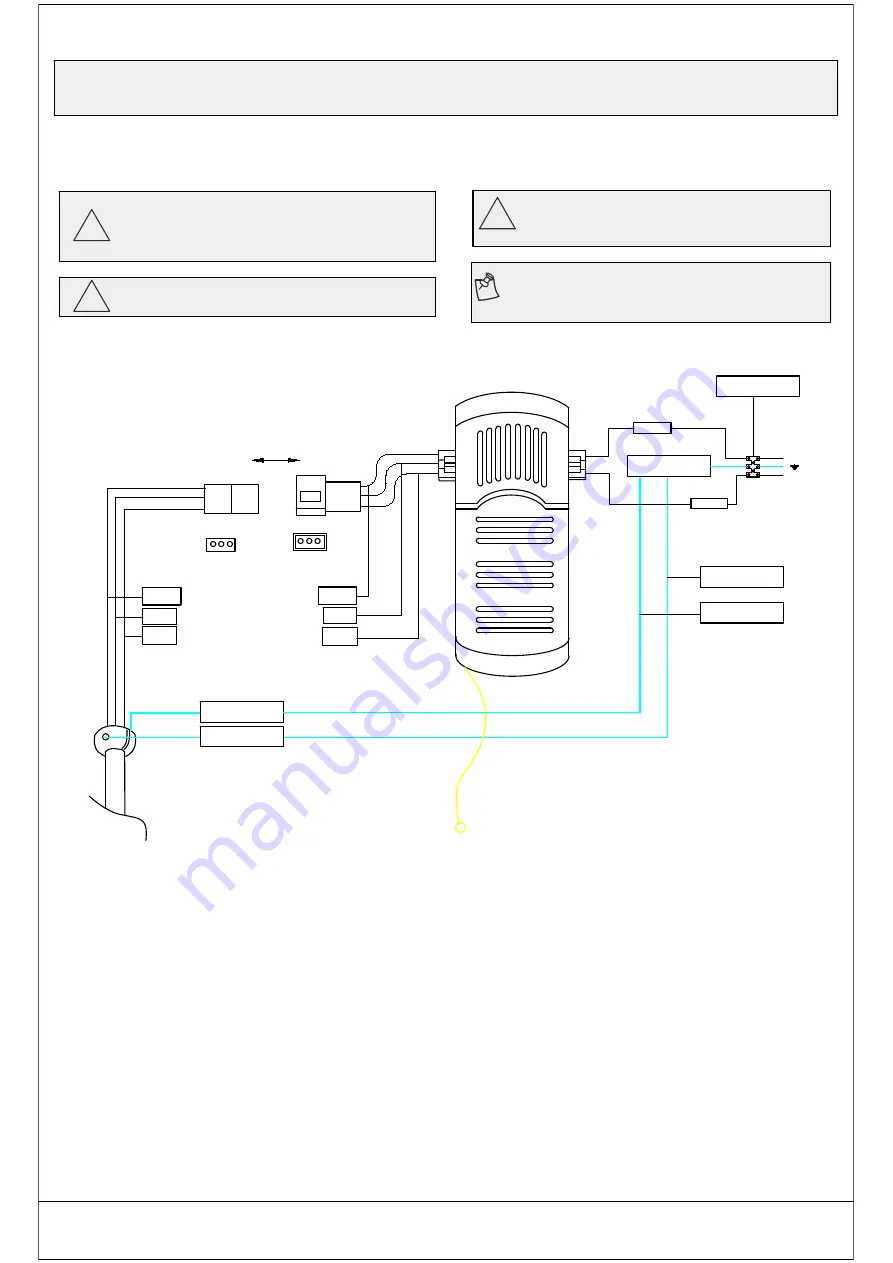
7. Making the electrical connections

!

WARNING: Check to gee that all connections are tight,
 including ground,and that no bare wire is visible at the
 connect Terminal blocks, except for the ground wire.

!

CAUTION: Do not use with a wall light dimmer switch

NOTE: The fan must be installed at a maximum distance of

20 ft from the remote control for proper signal transmission
between the remote control and the fan's receiving unit.

Yellow/Green

Neutral Wire for Fan

Live Wire for fan

Live Wire for Lamp Control

Yellow/Green

Terminal blocks

Ground wire

Ground wire

Antennd wire

L

N

Motor to receiver electrical connections:

1. Connect the fan wire with receiver wire by connect terminal. Receiver to house supply wires

    electrical connections:

1. Connect the receiver white wire marked "AC in N" to the household white wire (neutral) using

    a wire terminal block.

2. Connect the receiver Black wire marked "AC in L" to the household Black wire (hot) using a

    wire terminal block.

3. Connect the fan wire and the ground wire on the hanger through the terminal block.

4. Use the terminal block to connect the ground wire on the mounting bracket to the household
    ground wire.

Summary of Contents for AL03P01

Page 1: ...USE AND CARE GUIDE SI 52 INCH CEILING FAN IC AS MG AL03P01...

Page 2: ...Table of Contents 2 Safety Information 3 Warranty 4 Pre Installation 4 Operation 13 14 Care and Cleaning 14 Assembly 8 Assembly Hanging the fan 9 10 11 12 Pre Installation continued 5 6 Installation 7...

Page 3: ...with the limits for a Class B digital devico pursuant to Part 15 of the FCC Rules These limits are designed to provide reasonable protection against harmful interference in a residential installation...

Page 4: ...ng any accessories is not covered by this warranty Because of varying climatic conditions this warranty does not cover any changes in brass finish including rusting pitting corroding tarnishing or pee...

Page 5: ...F GG HH AA BB CC DD GG Part Description Quantity 16 1 1 10 2 2 Clevis pin preassembled Cotter pin preassembled Screws preassembled 5 6 5 FF EE HH Blade attachment hardware Extra blade bracket hardware...

Page 6: ...preassembled Canopy Hanger ball downrod assembly Coupling cover Part Description Quantity Remote control holder Remote control H L 1 1 5 1 Blade bracket flange screws pre installed Blade Fan motor ass...

Page 7: ...decorative canopy bottom cover and turn the canopy C 180 before attaching the canopy C to the mounting bracket A If your ceiling fan does not have an existing UL listed mounting box then install one u...

Page 8: ...es exiting the top of the fan motor assembly F through the downrod as shown 2 Loosen but do not remove the setscrew on the collar P on top of the motor housing 3 Align the holes at the bottom of the d...

Page 9: ...k the spots where the 4 Self Tapping Screws Il will be drilled 2 Remove the Mounting Bracket A dril 4 holes for 3MM diameter instal the mounting bracket onto wooden ceiling with the 4 Self Tapping Scr...

Page 10: ...t the receiver K into the mounting bracket A with the flat side of the receiver K facing the ceiling 5 Attaching the blades to the blade brackets 1 Attach a blade H to a blade bracket I by inserting s...

Page 11: ...the remote control for proper signal transmission between the remote control and the fan s receiving unit Yellow Green Neutral Wire for Fan Live Wire for fan Live Wire for Lamp Control Yellow Green Te...

Page 12: ...tch cup cover of the light kit fitter assembly G 4 Connect the wires from the light kit fitter assembly G to the wires from switch cup of the fan motor assembly by connecting the molded adaptor plugs...

Page 13: ...Press and release button one time will turn the light off M II Remove two remote control holder plugs from the remote control holder I Note that the plugs have unique tabs that allow them to fit only...

Page 14: ...Apply oil to your fan or motor The motor has permanenty lubricated sealed ball bearings Operation continued Cool weather Counterclockwise Direction An upward air flow moves warm air off the ceiling Th...

Page 15: ...re set to the same frequency Make sure all motor housing screws are Snug Make sure the screws that attach the fan blade to the motor hub are tight Make sure the wire nut connections are not rattling a...

Reviews: