warema_2052443_alhb_en_v3•2023-07-01
We reserve the right to make technical modifications
2
Install the weather station in an easily accessible
location at the highest point of the roof structure or
the facade side to be monitored. To avoid hindering
accurate wind evaluation, do not mount the device away
from the wind.
For the system to function properly, precipitation must
be able to hit the sensor surface without interference.
The supply line must be routed so that water cannot
enter into the device or into the building. Use weather-
proof (suitable for outdoor installation) cables such as
4 x AWG 26 C UL black.
The total line length from the weather station must
not exceed 200 m if a twisted paired line is used and
routed in an interference-proof manner.
Depending on the installation situation, you can
also directly route the line of type JY(St)Y to the
Omnexo weather station move. It must be ensured
that the line is protected against UV radiation (e.g.
in a conduit, tube) along its entire length.
The photodiode 1 is used for the dawn/dusk control.
The weather station should therefore be positioned so
that the photodiode cannot be influenced at night by
street or garden lighting or other external light sources
(e.g. flashlights).
Trees, bushes or parts of the building can shade the
sensor during the course of the day. In this case, the
sensor cannot deliver exact measuring values and the
results will be incorrect. Therefore, select the installation
location carefully.
The weather station can also be mounted on an
optionally available pole. This requires an additio-
nal fixing adapter (special accessory).
Electrical connection
An on-site overload current protection device (fuse) and a
disconnecting and isolating switch to switch off the entire
unit must be provided.
Use a line that is approved for the operating voltage
and is resistant to weather and UV rays (suitable for
outdoor use),
e.g. 4 x AWG 26 UL black.
The supply line must be routed so that water cannot
enter into the device or into the building.
The total line length must not exceed 1,200 m if a
twisted pair line is used and routed in an interference-
proof manner.
Pay attention to the minimum voltage at the weather
station (voltage drop) and use a separate power supply
unit for the power supply if necessary.
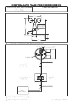
Connect the weather station to the Omnexo Central
control unit as per wiring diagram Fig. 4 on page 4.
The bus lines must be provided with terminating
resistors at the beginning and end of the line.
HUBs are needed for longer line lengths.
If you are using the optional Omnexo Weather station
pro power supply unit 24 V DC/1.3 A AP (article
number 2057430), a branch line of max. 10 m to the
Omnexo Weather station move is permissible.
Please take out the WAREMA ID labels from the devices
and give them to your system integrator (see also
page 4). A clear allocation of the devices and ID labels
must be ensured.
This device meets the requirements on electromagnetic
immunity and electromagnetic interference for use in
residential and commercial environments.
If the Omnexo Weather station move is the last
bus device in the bus line, the terminating resistor
needs to be manually set (see Fig. 4 on page
4).
Depending on the installation situation, you can
also directly route the line of type JY(St)Y to the
Omnexo weather station move. It must be ensured
that the line is protected against UV radiation
(e.g. in a conduit, tube) along its entire length.
Commissioning
To be able to commission the weather station, it must be
set up in the Omnexo software. To determine the serial
number, place the magnet (in central control unit scope of
delivery) on the right side of the housing (photo 2) until the
status LED lights up for confirmation. (see Fig. 3 on page
4).
Alternatively, you can manually enter the serial number
manually (see label on device).
When commissioning, note that the weather station
has an internal temperature correction feature that
improves measurement accuracy. A change in tem-
perature is displayed with a delay of 10 minutes
per °C.
When the operating voltage is first switched on, a
temperature measurement is taken at the weather
station. If the weather station was previously stored
at a considerably lower or higher temperature, it
may take several hours before the correct tempera-
ture is displayed.
If the weather station is already at the temperature
of its environment when it is first switched on, the
actual temperature measurement value will be dis-
played from the start.
Allocation of the photodiodes
The numbers 1 to 4 have been factory-assigned to the
four photodiodes (see Fig. 2). Therefore, position the
photodiodes according to the building facades being
shaded. Align photodiode 1 to the northernmost facade.
For installation directly on the facade, align photodiode 1 to
the facade.
Pho
to
1
(Dämmerung)
Pho
to
3
Photo 4
Photo 2
Fig. 2 Position of the photodiodes on the device


