background image

Installation

Page 2 | 8

2021216 [Rev. 2 - en]/2017-04-19

2

Installation

INFO

The fixing holes shall be planned according to the
mounting substructure (recommendation: wood =
∅ 2.0 mm, plastic/aluminium = ∅ 2.8 ).

2.1

Scope of delivery

INFO

Check the scope of delivery against the delivery

note.
Check the parts to make sure they are not

damaged.
Compare the situation on-site with the details

provided in the order.
If any items are damaged or not as specified

in the order, stop installation and contact

WAREMA.

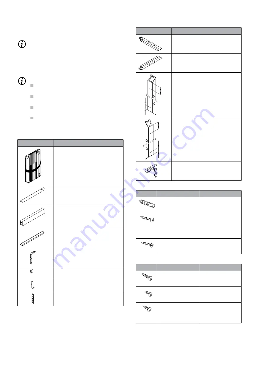
Parts description

Package (pleated blind with handle

rail in P1.Q.xx)

or

Package (two pleated blinds with

handle rails in P2.Q.xx)

Ceiling profile 15x10 mm

Guide rail, top, 18x35 mm

Base profile 18x7 mm

Fixing bracket, top (2 pieces)

Mounting plate for fixing bracket, top

(2 pieces)
Fixing bracket, bottom (2 pieces)

Clip holder, middle (2 pieces)

Tab. 2:

Overview of parts in P1/2.Q.20-23

Parts description

Mounting frame profile, top

Additional drilled holes exist for se-

curing the ceiling profile.

Mounting profile, bottom (in

P1/2.Q.21)

39

100

Mounting profile, right

In P1/2.Q.22, no mitre cut at the bot-

tom.

In P1/2.Q.23, no mitre cut and fixing

holes in the same surface.

100

39

Mounting profile, left

In P1/2.Q.22, no mitre cut at the bot-

tom.

In P1/2.Q.23, no mitre cut and fixing

holes in the same surface.

Corner joint connectors

P1/2.Q.21 (4 pieces)

P1/2.Q.22 (2 pieces)

Tab. 3:

Overview of parts in P1/2.Q.21-23

Designation

Use

Screw anchor SX

6x30

Ceiling profile, clip-

holder, mounting

frame/profiles

Chipboard screw

4x40 AW20 with pan

head

P1/2.Q.20: Ceiling

profile, clip holder

P1/2.Q.21/22/23:

mounting frame/pro-

files

Chipboard screw

4x40 AW20 with

countersunk head

P1/2.Q.20: Fixing

brackets, top/bottom

Tab. 4:

Fixing material on masonry (P1/2.Q.20/21/22/23)

Designation

Use

Pan head self-tap-

ping screw DIN 7981

3.5x25 AW10

P1/2.Q.21/22/23:

Mounting frame/pro-

files

Pan head self-tap-

ping screw DIN 7981

3.5x9.5 AW10

P1/2.Q.20/23: Ceiling

profile, clip holder

Countersunk head

tapping screw

DIN 7982 3.5x13

AW10

P1/2.Q.20: Fixing

brackets, top/bottom

Tab. 5:

Fixing material on plastic/aluminium

(P1/2.Q.20/21/22/23)

Summary of Contents for P2.Q Series

Page 1: ...se qualifications the work must be carried out by a specialist fitting company Contents These instructions are an integral part of the following product Insect screen pleated blind P1 Q xx one wing and P2 Q xx two wing Intended use The following details apply to the following product Insect screen pleated blind P1 Q xx one wing and P2 Q xx two wing The product is a horizontally movable insect scre...

Page 2: ... for se curing the ceiling profile Mounting profile bottom in P1 2 Q 21 39 100 Mounting profile right In P1 2 Q 22 no mitre cut at the bot tom In P1 2 Q 23 no mitre cut and fixing holes in the same surface 100 39 Mounting profile left In P1 2 Q 22 no mitre cut at the bot tom In P1 2 Q 23 no mitre cut and fixing holes in the same surface Corner joint connectors P1 2 Q 21 4 pieces P1 2 Q 22 2 pieces...

Page 3: ...ge of opposite side Top edge of ceil ing profile to bottom edge of base profile P1 2 Q 21 Mounting frame di mensions Mounting frame di mensions P1 2 Q 22 Mounting frame di mensions Top edge of mount ing frame to bottom edge of base profile P1 2 Q 23 Back edge of lateral mounting profile Top edge of ceil ing profile to bottom edge of base profile Tab 8 Order width and order height depending on mode...

Page 4: ...he mounting frame Attach the ceiling pro file P1 2 Q 23 Hold the ceiling profile between the mounting profiles on the mounting substructure Transfer the drill hole position Drill the fixing holes Attach the ceiling pro file Attaching the base profile P1 2 Q 20 23 Slide the fixing brack ets into the base profile at the bottom on both sides INFO The fixing brackets at the bottom can be shifted in th...

Page 5: ...d Inserting the pleated blind in the ceiling and base profiles 2 1 3 Insert the package in the guide rail Lower the package into the base profile Remove the safety straps on the package Attaching the end profiles INFO First attach the end profile of the package side 2 1 Swing in the end profile at the top Press on the end profile to hook it into the brack et 2 1 Press the end profile against the m...

Page 6: ...and a long service life CAUTION Risk of injury from falling from climbing aid Climbing aids e g ladders scaffolding etc may tip over if improperly erected Position climbing aids on level and firm ground Do not rest climbing aids against the product CAUTION Risk of injury from falling There is a risk of falling during maintenance work Take suitable safe measures to prevent or stop a fall 3 1 Cleani...

Page 7: ...by the GRM Gütegemeinschaft Reinigung von Fassaden e V certification no 142 242 342 442 542 To order contact your WAREMA dealer For further advise and in technical matters regarding cleaning please contact the Verband Deutscher Sonnenschutzreiniger e V www vds sonnenschutz de Preparing cleaning When cleaning the product protect adjacent areas against soiling Aids required for cleaning Soft brush d...

Page 8: ...ed by a qualified specialist according to the WAREMA maintenance checklist The maintenance checklist is available from your specialist dealer or can be requested from WAREMA 3 3 Spare parts repairs INFO To ensure that your product will operate properly on a continuous basis and to avoid changing its approved status use original spare parts only Contact your WAREMA specialist dealer if necessary 3 ...

Reviews: