Installation
2021216 [Rev. 2 - en]/2017-04-19
Page 3 | 8
Designation
Use
Chipboard screw
3.5x25 AW20 with
pan head
P1/2.Q.21/22/23:
Mounting frame/pro-
files
Chipboard screw
3.5x15 AW20 with
pan head
P1/2.Q.20/23: Ceiling
profile, clip holder
Chipboard screw
3.5x16 AW20 with
countersunk head
P1/2.Q.20: Fixing
brackets, top/bottom
Tab. 6:
Fixing material on wood (P1/2.Q.20/21/22/23)
Designation
Use
Pan head self-tap-
ping screw DIN 7981
3.5x9.5 AW10
Ceiling profile/clip
holder
Countersunk head
tapping screw
DIN 7982 3.5x13
AW10
Fixing brackets, top/
bottom
Tab. 7:
Fixing material for small parts on mounting frame/
profiles (P1/2.Q.21/22/23)
2.2
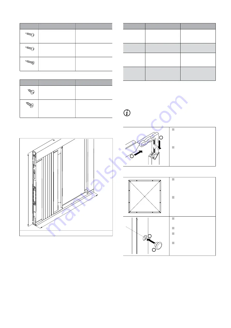
Product position
B
H
B
Order width
H
Order height
Fig. 2:
Dimensional drawing P1.Q.20
Order width B
Order height H
P1/2.Q.20
Back edge of pack-
age to back edge of
opposite side
Top edge of ceil-
ing profile to bottom
edge of base profile
P1/2.Q.21
Mounting frame di-
mensions
Mounting frame di-
mensions
P1/2.Q.22
Mounting frame di-
mensions
Top edge of mount-
ing frame to bottom
edge of base profile
P1/2.Q.23
Back edge of lateral
mounting profile
Top edge of ceil-
ing profile to bottom
edge of base profile
Tab. 8:
Order width and order height depending on model
2.3
Installing the mounting frame
(P1/2.Q.21/22)
Connecting the mounting frame
INFO
In model P1/2.Q.22, the mounting frame is open at
the bottom.
1
2
Push the corner joint
connector into the
mitres on two mounting
frame profiles.
Slide the mounting
frame profiles (mitre
side) onto the corner
joint.
Attaching the mounting frame
D1
D2
Hold the mounting
frame against the re-
veal. Watch the edge
distances.
Check diagonals D1
and D2. Align the
mounting frame if nec-
essary.
1
2
Transfer the drill hole
position.
Drill the fixing holes.
Attach the mounting
frame.
Press the cover caps in-
to place.


