2005613_a•en•2017-09-01
We reserve the right to carry out improvements
16
Sensor Splitter
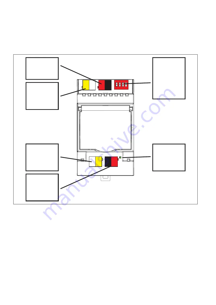
5 Wiring diagrams
D1
X6
S2
X5
1 2 3 4
ON
X10
X11
0V 24V A B
24V 0V B1 A1
Terminals X6
Connection to
the bus
of the central
control unit
Terminals X5
Connection of
the 24 V DC
power supply
Terminals X10
Power supply
for weather
station
(max. 250 mA)
Terminals X11
Bus connection
for the weather
stations
Service-LED
Display of bus
communication
Encoding
switch S2
Definition of the
master,
Disabling of
addresses
Fig. 6
All connections at a glance


