background image

2005613_a•en•2017-09-01

We reserve the right to carry out improvements

27

Sensor Splitter

climatronic 1

climatronic 2

Sensor splitter 1

MASTER

Sensor splitter 2

SLAVE

Weather station

1

RD

BK

RD

BK

BK  RD

BK  RD

R

R

R

R

R

R

R

= Terminating resistor

climatronic 1

climatronic 2

Sensor splitter 1

MASTER

Sensor splitter 2

SLAVE

Weather station

2

RD

BK

RD

BK

BK  RD

BK  RD

R

R

R

R

R

climatronic 2

Sensor splitter 2

SLAVE

BK  RD

R

climatronic 1

Sensor splitter 1

MASTER

Weather station

3

RD

BK

RD

BK

BK  RD

R

R

R

R

Output state or
final state of 
bus wiring

Bus wiring
for commissioning
of climatronic 1

Bus wiring
for commissioning
of climatronic 2

Sensor bus

climabus 1

climabus 2

climabus 1

climabus 2

climabus 1

climabus 2

Sensor bus

Sensor bus

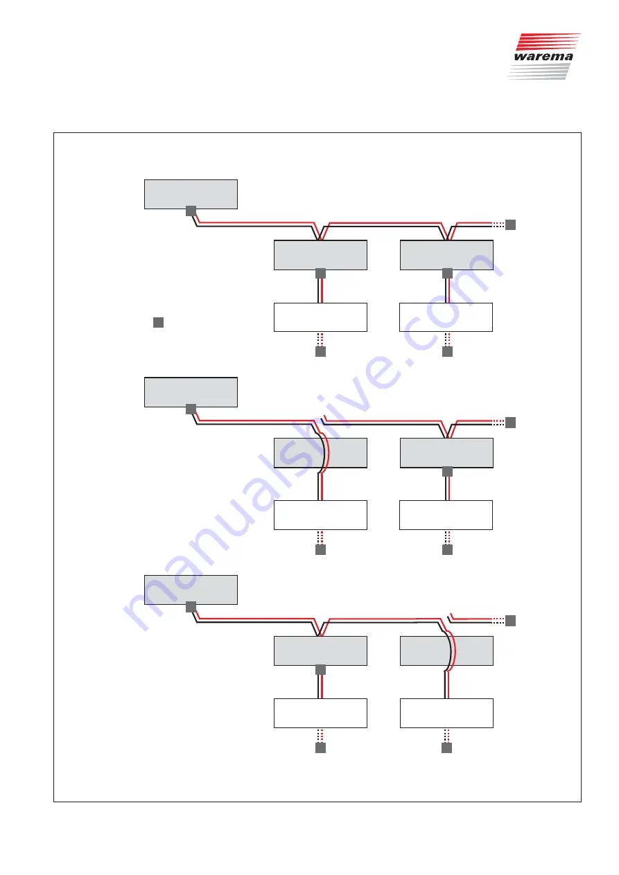
Fig. 15 

WAREMA climatronic

®

: bus connection during commissioning

Summary of Contents for Sensor Splitter

Page 1: ...Sun Light WAREMA Photo Habermaass GmbH Sensor Splitter Installation instructions Keep for future use Valid from 01 September 2017 2005613_a en...

Page 2: ...ce WAREMA Renkhoff SE Hans Wilhelm Renkhoff Strasse 2 97828 Marktheidenfeld Germany P O Box 13 55 97822 Marktheidenfeld Germany Phone 49 9391 20 0 Telefax 49 9391 20 4299 http www warema com info ware...

Page 3: ...1 Connection information 12 4 2 Bus lines 13 4 3 Hardware settings on the sensor splitter 14 5 Wiring diagrams 16 5 1 Connecting the Wisotronic 18 5 2 Connecting the WAREMA climatronic 20 5 3 Connecti...

Page 4: ...units can be supplied with the necessary weather data from a single weather station The measuring values are actively requested from the connected weather stations via the sensor splitter All other s...

Page 5: ...ions for future use 2 1 Meanings of symbols and pictographs The safety information in these instructions is marked with warning symbols It is categorised into different warning types depending on the...

Page 6: ...nger WARNING Warning against dangerous electrical voltage CAUTION Component damage due to electrostatic discharge NTTE The term NTTE marks important information and helpful tips TEEample The term TEEa...

Page 7: ...alist dealer if you need additional information WARNING Mounting connection commissioning or operation by insufficiently qualified and knowledgeable persons may cause serious damage to the system or e...

Page 8: ...ulations must be observed under all circumstances Make sure to always use suitable electrical tools WARNING States of danger malfunctions and property damage to the unit may arise from improperly eEec...

Page 9: ...ctions and use of the device in a manner that contravenes its intended use and purpose may result in the manufacturer refusing to honour warranty claims for prod uct damage In this case liability for...

Page 10: ...mes void Follow the points below in the order given First determine where the individual components are to be installed Use the instructions given in Chapter 4 1 on page 12 Then determine which cables...

Page 11: ...be subjected to direct sunlight Please observe the cable types recommended in the wiring diagrams When installing the devices in a distributor they must be mounted on a sym metrical DIN rail 35 mm as...

Page 12: ...re recommendations As specified in VDE 0022 the operating company and the installer are responsible for compliance with the regulations put forth by the public utility provider and the VDE The wiring...

Page 13: ...of the central control unit terminals A and B with the bus connections for the weather stations ter minals A1 and B1 See Fig 6 on page 16 A maximum of 200 sensor splitters can be operated in a system...

Page 14: ...found in Table Fig 5 This setting should always be made with the device switched off TEncoding switch Setting Comment 1 ON MASTER The connected central control unit queries data directly from the weat...

Page 15: ...2005613_a en 2017 09 01 We reserve the right to carry out improvements 15 Sensor Splitter...

Page 16: ...minals X6 Connection to the bus of the central control unit Terminals X5 Connection of the 24 V DC power supply Terminals X10 Power supply for weather station max 250 mA Terminals X11 Bus connection f...

Page 17: ...s 4 outputs X10 1 24 V Power supply for weather station max 250 mA 2 0 V X11 1 B1 Communication RS485 2 A1 TEncoding switch S2 1 ON MASTER The connected central control unit queries the data directly...

Page 18: ...he weather station to the sensor splitter that is acting as the MASTER Provide separate on site fuse protection for the sepa rate power supply unit This ensures that weather data will always be sent t...

Page 19: ...g resistor 120 JY St Y 2x2x0 8 mm WT RD BK 0V B A BK RD WT YE Terminating resistor 120 RD BK YE WT Wisotronic 1 channel JY St Y 2x2x0 8 mm Sensor bus CAUTION The 24 V output terminals X10 of the senso...

Page 20: ...the sensor splitter that is acting as the MASTER Providing a separate power supply unit with its own on site fuse protection ensures that weather data will always be sent to the sensor bus NTTE The s...

Page 21: ...X10 of the sensor splitters must not be connected to each other Junction box On site Weather station JY St Y 2x2x0 8 mm 24V 0V A B 4xAWG 26 C UL black Terminating resistor integrated JY St Y 2x2x0 8...

Page 22: ...ather stations should always have their own power supply unit Providing a separate power supply unit with its own on site fuse protection ensures that weather data will always be sent to the sensor bu...

Page 23: ...nected instead of a weather station Terminating resistor 120 JY St Y 2x2x0 8 mm YE WT RD BK Sensor Interface Terminating resistor 120 X5 Input X6 RS485 Prog X7 0V 24V A B ID LED 15V 0V 15V 1 JY St Y 2...

Page 24: ...ic control panel and the weather station multisense already have an integrated 120 terminating resistor Total length of the RS485 bus maximum 1200 m The bus voltage must be at least 20 V at each devic...

Page 25: ...tant that you adhere to the described sequence or else it will not be possible to commission the unit properly Check that all bus lines are correctly wired see Chapter 5 1 on page 18 Check that all en...

Page 26: ...e instructions ac companying the climatronic NTTE Learn in the weather stations into the same positions on all WAREMA cli matronic control panels e g weather station 1 When you learn in a weather stat...

Page 27: ...ensor splitter 2 SLAVE Weather station 2 RD BK RD BK BK RD BK RD R R R R R climatronic 2 Sensor splitter 2 SLAVE BK RD R climatronic 1 Sensor splitter 1 MASTER Weather station 3 RD BK RD BK BK RD R R...

Page 28: ...on Power supply Spring terminals 0 6 0 8 mm Network Spring terminals 0 6 0 8 mm Test standards EN 61000 6 2 2005 EN 61000 6 3 2007 A1 2011 EN 50428 2005 A1 2007 A2 2009 EN 60950 1 2006 A11 2009 A1 201...

Page 29: ...bus switched on sufficiently sized Encoding switch S2 1 set to ON on multiple sensor splitters Set the encoding switch S2 1 to ON on only one sensor splitter Encoding switch S2 1 set to OFF on all sen...

Page 30: ...her station multisense on the Wisotronic Proceed as follows to replace a faulty weather station multisense Switch off the power supply of the weather station multisense Replace the weather station mul...

Page 31: ...tation Follow the instructions accompanying the climatronic Complete the procedure with Load a weather station or Load all devices Load data in the devices menu Switch the power supply for climabus 1...

Page 32: ...ff Strasse 2 97828 Marktheidenfeld Main Germany http www warema de info warema de KEEP IN A SAFE PLACE FOR COMMISSIONING Note down installation location here Notes on commissioning e g special feature...

Reviews: