890013_f•en•2015-11-01
We reserve the right to carry out improvements
2
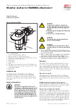
The inclination of the sensor surface creates the required
angle to allow the water to drain off the sensor surface.
Openings to record wind
Four openings with sensors, arranged at right angles,
record the wind speed. The direction of the wind is deter-
mined by calculating the difference in the sensor values.
Installation
Use the included mounting hardware to mount the weather
station.
■
The weather station must be mounted in an upright
position with a maximum inclination of ±2°. The photo-
diodes must be at right angles to the building facades
being shaded. Position photodiode 1 to face as north-
ward as possible.
■
The weather station should be mounted easily acces-
sible on the highest point of the roof structure or the
conservatory. To prevent interference with the wind
evaluation, do not mount the device away from the
wind.
■
For the system to function properly, precipitation must
be able to hit the sensor surface from any direction
without interference.
■
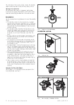
The supply line must be routed so that water cannot
enter into the housing (see Fig. 1). Use weather-resist-
ant (suitable for outdoor installation) cables such as
4x AWG26C UL bl!
■
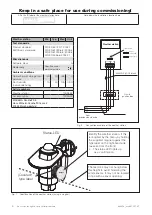
The photodiode 1 controls the dawn/dusk control (see
Fig. 2). The weather station should therefore be posi-
tioned so that the photodiode cannot be influenced at
night by street or garden lighting or other external light
sources (e.g. flashlights).
■
Metal-clad buildings, domestic interference sources
(unshielded household appliances, television sets,
computers), supply lines and metallic objects such as
sheet metal enclosures, must have a distance of at
least 0.5 m from the sensor. Check the radio clock re-
ception prior to final installation.
Trees, bushes or parts of the building can shade the
sensor during the course of the day. In this case, the
sensor cannot deliver exact values and the results will
be incorrect. Therefore, select the installation location
carefully.
Assignment of the photodiodes
The numbers 1 to 4 have been factory-assigned to the
four photodiodes; see Fig. 2.
Pho
to
1
(Dusk)
Pho
to
3
Photo 4
Photo 2
Fig. 2
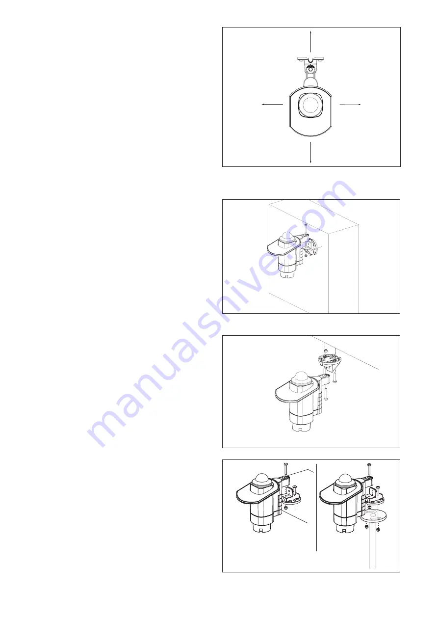
Alignment of the photodiodes
Installation options
Fig. 3
Wall mounting
Fig. 4
Ceiling mounting
Fig. 5
Roof mounting / Standpipe mounting

