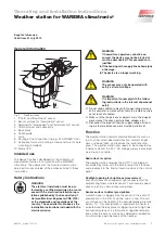
3
890013_f•en•2015-11-01
We reserve the right to carry out improvements
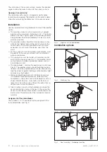
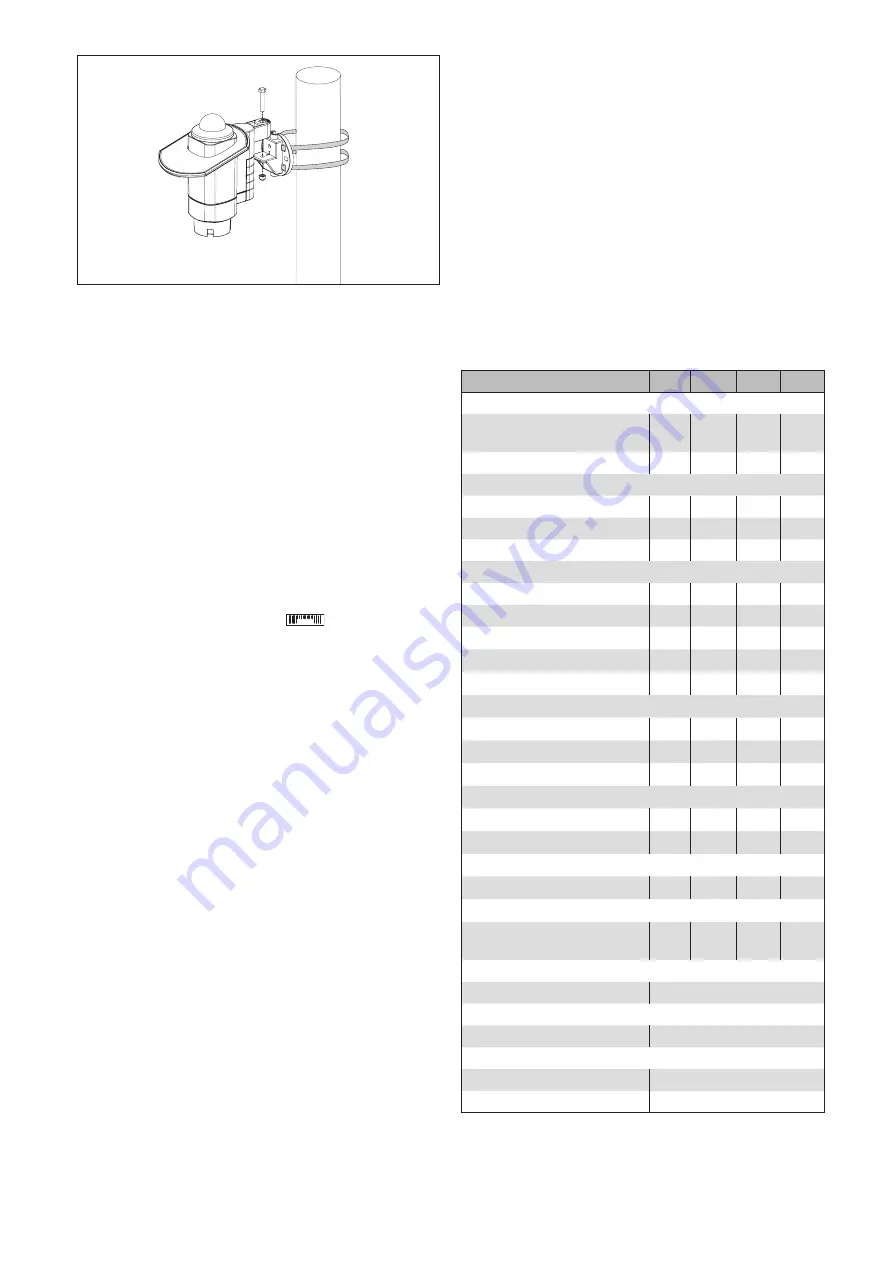
Fig. 6
Pole mounting: Make sure that the cable ties are guided
through the slots and that the projections of the locking
closures point outward.
Electrical installation
An on-site overload current protection device (fuse) and a
disconnecting and isolating switch to switch off the entire
system must be provided.
The device meets the EMC directives for use in residential
and commercial areas.
When performing the electrical installation, please note the
following:
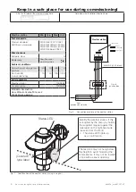
The max. bus line length between the first and last bus
device must not exceed 1200 mm.
Repeaters/HUBs are needed for longer line lengths.
A line structure must be adhered to. Branch lines are
only possible with repeaters or HUBs!
Please take out the ID labels
WAREMA ID
from the devices
and give them to your system integrator (see also
page 4). A clear allocation of the devices and ID labels
must be ensured!
The bus lines must be provided with terminating resis-
tors at the beginning and end of the line.
Commissioning
To be able to commission the weather station, it must be
set up and identified in the WAREMA climatronic control
panel. This is performed either in the assistant or manually
(see installation instructions art. no. 2003 869). To identify
the device (determining the serial number), place the sup-
plied magnet on the type plate at the right outside surface
of the housing until the status LED lights up for confirmati-
on (see Fig. 8). Alternatively, you can enter the serial num-
ber manually in the operating unit.
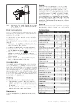
Cleaning
The weather station must be cleaned every 3 months.
■
Clean the device with a soft damp cloth. Steam or
high-pressure cleaners, abrasive sponges, abrasive
agents, and solvents such as alcohol or benzine may
not be used.
■
The openings for the wind measurement may only be
blown through. Never insert sharp objects.
Maintenance
There are no parts within the device that require mainte-
nance.
Liability
Failure to comply with the product information in these
instructions and use of the unit in a manner that contra-
venes its intended use and purpose may result in the
manufacture refusing to honour warranty claims for prod-
uct damage. In this case, liability for consequential harm
to persons or damage to property will also be excluded.
Follow the instructions in the operating instructions of your
sun shading system. The automatic or manual operation
of the sun shading system when it is iced over, and use of
the sun shading system during severe weather, may cause
damage and must be prevented by the user by taking suit-
able precautions.
Disposal
After its use, the device must be disposed off according to
legal regulations or returned to your local recycling centre.
Technical data
Weather station
Min. Typ. Max. Unit
Supply
Operating voltage (SELV)
20
24
28
V
DC
Current consumption
92
160
250
mA
Temperature sensor
Measuring range
-30
+60
°C
Resolution
0.5
°C
Accuracy
±0.5
°C
4 direction-dependent photo sensors
Measuring range
0
100
kLx
Resolution during daytime
1
kLx
Accuracy during daytime
1
kLx
Resolution at dawn/dusk
2
Lx
Accuracy at dawn/dusk
10
Lx
Wind speed
Measuring range
0
25
m/s
Resolution
1
m/s
Accuracy
±1
m/s
Wind direction
Measuring range
0
360
°
Accuracy
45
°
Radio clock reception
Frequency
77.5
kHz
Precipitation sensor
Surface temperature of the
sensor surface when heated
40
°C
Dimensions
WxHxD
84x140x160 mm
Installation
Wall/ceiling/pole
Degree of protection/safety class
Degree of protection
IP 43
Safety class
III

