890013_f•en•2015-11-01
We reserve the right to carry out improvements
4
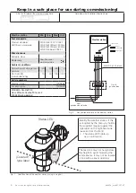
1 2 3 4
Weather station
Onsite
junction box
from
previous bus device
JY(St)Y 2x2x0.8mm ø
X1
J1
Bus B
0V
A
B
24V
Bus A
24 V
0 V
4xAWG 26C UL black
Network
closed (120Ω)
Network open
Terminal strip J1
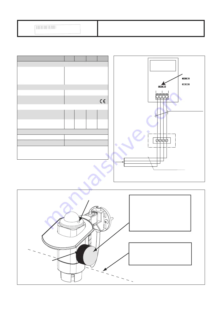
Fig. 8
Connection example of the weather station
Weather station
Min. Typ. Max. Unit
Test standards
Product standard:
EMC basic standards:
DIN EN 60730-1: 2002-1
DIN EN 61000-6-2: 2002-8
DIN EN 61000-6-3: 2002-8
DIN EN 50366: 2003-11
Miscellaneous
Software class
A
Conformity
Specified under
www.warema.de
Ambient conditions
Operating and storage tem-
perature
-30
20
+60
°C
Rel. humidity
(non-condensing)
10
40
100 %RH
Article numbers
Weather station
1002662
Accessory box
1002022
WAREMA Renkhoff SE
Hans-Wilhelm-Renkhoff-Strasse 2
97828 Marktheidenfeld
Identify the weather station, if this
is required by the menu, by holding
the supplied magnet against the
type label on the right-hand side
(as seen from the front).
-> The status LED lights up
as a confirmation.
Status-LED
Magnet
The feed line may not hang below
this height to avoid hindering the
wind sensors. It may not be located
in line with a sensor opening.
(Covered)
type label
Fig. 7
Identification of the weather station (using a magnet)
Keep in a safe place for use during commissioning!
Affix the ID label of the weather station here.
00001372
Wetterstation
Note down the installation location here.

