background image

9

2024730_d•en•2020-01-01

We reserve the right to make technical modifications

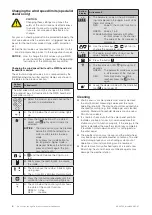
Liability

Failure to comply with the product information contained in 

these instructions and any use of the device other than its 

intended use and purpose may result in the manufacturer 

refusing to honour warranty claims for product damage. 

In this case, liability for secondary harm to persons or 

damage to property will also be excluded. In addition, be 

sure to observe the information contained in the operating 

instructions for your sun shading system. The automatic 

or manual operation of the sun shading system when iced 

over as well as using the sun shading system during se-

vere weather may cause damage and must be prevented 

by the user by taking suitable precautions. 

OTICE 

N

This device meets the requirements on elec-

tromagnetic immunity and electromagnetic 

interference for use in residential and commer-

cial environments.

Maintenance

Strong vibrations at the installation location (for exam-

ple, from frequent high wind loads) can loosen the fixing 

screws. If the joint screw is not properly tightened, the 

alignment of the weather station may change as well.


Therefore, check from time to time that the weather 

station is still firmly installed and that all screws are 

sufficiently tight.

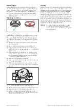
Replacing the battery

   VAR

TA    V65HT

CR 1632

 Li-Mn    3V

Fig. 10  Correct batteries

When a button is pressed on the weather station, no LED 

lights up. The charge status of the batteries is too low. If 

the weather station still does not work after charging via 

the USB port, the batteries must be replaced. Proceed as 

follows:


Remove the cover of the weather station with a cross-

head screwdriver. 


Set the switch on the printed circuit board to "off".


Always replace all three batteries. Only batteries of 

type VARTA V65 HT (accessories kit, art. no. 2029295) 

may be used.


When inserting the new batteries, make sure that the 

polarity matches: the positive terminal (+) of the batter-

ies should face up (visible) and the negative terminal 

(-) should face down (see Fig. 4).


Only touch the batteries at the edge.


When inserting the batteries, take care not to damage 

the printed circuit board.


When inserting the batteries, make sure that the bat-

teries are pushed to one side under the contacts (see 

Fig. 10).

VAR

TA V

65

 H

T

Fig. 11  Inserting batteries correctly under the contacts


Set the switch on the printed circuit board back to "on".


Screw the cover of the weather station back on.


Batteries may leak and damage the device. If the 

device will not be used for an extended period of time, 

please remove the batteries.

Summary of Contents for WMS Weather Station Eco

Page 1: ...uded cable ties Included fixing materials 2 screws 4 5 x 40 mm 2 screw anchors 6 mm 2 spacers for wall and ceiling installation Fig 2 2 steel cable ties 360 mm Use suitable fixing materials only Depending on the sub structure e g plastered outer insulation other screws and screw anchors may need to be used Important information on the installation loca tion Attach the device outdoors at a readily ...

Page 2: ...urrents otherwise the sensor will not provide the correct wind evaluation Separate spacers are included for wall and ceiling installation They prevent cracking and deformation of the plastic Fig 2 Fig 2 Clipping the separate spacers into the threaded hole Additional installation information can be found in the documentation of your sun shading system Mounting plate 0 13 75 4 5 9 0 207 5 199 4 5 9 ...

Page 3: ...he button Initial operation You can find instruction videos on our YouTube channel at http www youtube com user SonnenLichtManager videos We recommend commissioning using the PC software WMS studio pro Activate the WMS weather station by flipping the switch on the printed circuit board to on Learning can then be started immediately The WMS weather station will now be in learn mode for two minutes ...

Page 4: ...twork OTICE N When you delete sensors from the network they are deleted from all reachable receivers in the network The control functions of the receivers remain active and must be separately deactivated for each receiver If for example wind monitoring was set for a receiver the product is automati cally retracted to protect it against damage if the heartbeat function fails Example 1 Delete the we...

Page 5: ...itter is described in the operating instructions of the WMS Central transmitter Button display Action result On the WMS hand held transmitter com fort select the product type and channel to which you wish to allocate the weather station Press the learn button on the WMS hand held transmitter comfort briefly lights up green and the product button and selected channel flash Brief On the weather stat...

Page 6: ...comfort Control functions Switching the comfort control functions on off You can switch the comfort controls off and on temporarily to prevent the sun shading products from moving automat ically The command always applies to all receivers that were learned into the WMS transmitter Safety functions cannot be switched on and off Button display Action result Wake up the WMS hand held transmitter comf...

Page 7: ...llowing table shows the limit values that the display values of the LED lines on the WMS hand held transmitter comfort represent Display of the limit values set in the receiver The WMS hand held transmitter comfort converts the limit values read out of the receiver to values that can be displayed on the 10 LEDs in the upper row of LEDs The displayed limit values therefore only approximate the limi...

Page 8: ...de The LED above the number 0 briefly lights up in green The sun control is displayed automatically Press the info button repeatedly until the symbol for the wind monitoring lights up The LED below the control symbol shows the state of the control function GREEN Active RED Inactive Button display Action result e g The parameter value of the wind monitor ing is displayed in the upper row of LEDs he...

Page 9: ...o time that the weather station is still firmly installed and that all screws are sufficiently tight Replacing the battery VARTA V65HT CR 1632 Li Mn 3V Fig 10 Correct batteries When a button is pressed on the weather station no LED lights up The charge status of the batteries is too low If the weather station still does not work after charging via the USB port the batteries must be replaced Procee...

Page 10: ...o low 5 s Activating the WMS weather station s radio module The WMS weather station has not yet been added to a network sliding switch is open I Press the button for at least 5 s The LED flashes GREEN three times The radio module is activated for two minutes During this time the LED flashes green every 5 seconds If the LED does not flash twice the WMS weather station s charge is too low Command fr...

Page 11: ...yp max Unit Supply Operating duration with full buffer in darkness 0 lx 5 days Ready for operation when connected via USB charger imme diate RF transceiver Transmission frequency 2 40 2 48 GHz Transmission power 10 dBm Reception sensitivity 101 dBm Operating range environment without inter ference 30 m Readings Wind speed intervals 0 5 m s 0 25 m s Brightness intervals 0 5 klx 0 100 klx Dawn dusk ...

Page 12: ...set too low Set the correct wind speed limit after con sulting the specialist dealer The wind speed limit depends on the most wind sensitive product controlled by the weather station The sun shading system does not raise in high winds The wind speed limit is set too high Lower the wind speed limit The weather station is installed in an area protected against the wind Check the installation locatio...

Reviews: