background image

12

1.800.556.0595


for assistance 

AIR CONDITIONING

AC Installation

Warmboard thermostats offer single-stage air 
conditioning. Connecting an AC system to WCS  
is very similar to wiring a 24v thermostat from  
an AC unit, just follow the steps below.


f

Remove the front cover from Warmsource-E


f

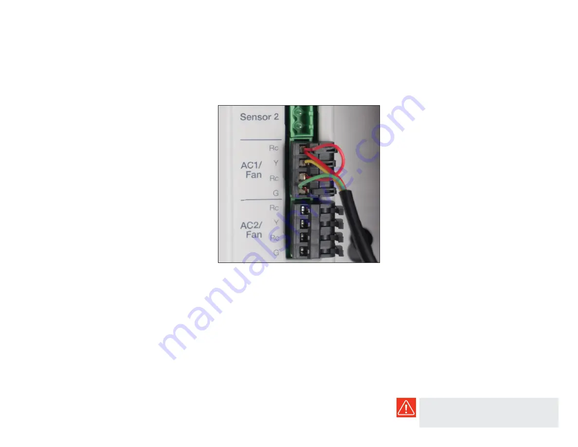
Locate terminal connection “AC1/Fan” on the  
Smart Reset Controller (SRC)


f

Connect the wires from the AC unit to the terminal 
block accordingly: 
 

RC

:  24 volt power (red wire) 


Y

:  Cooling Call (yellow wire) 


G

:  Fan (green wire)


f

To activate the “Fan Only” feature, use a small jumper 
wire between the two RC ports on the terminal block


f

Repeat for “AC2/Fan” if using air conditioning across 
two cooling zones


Some AC solutions require their own proprietary 
controls. In these instances, WCS thermostats 

CANNOT

 be used to control the cooling.

Summary of Contents for Comfort System

Page 1: ...For use with Warmsource E electric boiler WARMBOARD COMFORT SYSTEM 0622 Installation Guide...

Page 2: ...e the ambient air temperature near the Warmsource E does not exceed 90 F 32 C during operation 6 Reference the Electro Boiler Manual for allowable mineral levels and water quality Filtered water or a...

Page 3: ...s list can be a helpful when working with Warmboard S and WCS f Foundation and joist f Install Warmboard S f Install tubing some loops before walls f Frame walls roof sheeting f Install tubing manifol...

Page 4: ...be reset with a bike pump and ball valve in the closed position f Backflow preventer required by code in many jurisdictions prevents water in the closed loop system from mixing with the domestic wate...

Page 5: ...e piping can be found in the WCS Design Drawings f Pressure test all distribution lines for 15 minutes at 100 PSI International Mechanical Code section 1208 1 Minimum Clearances This illustration show...

Page 6: ...it Air Eliminator 51 2 331 2 33 4 41 2 253 8 1 11 4 conduit 1 2 3 4 conduit 131 4 51 2 21 4 61 8 3 41 8 91 2 Pressure Relief Drain connection 3 4 NPT 1 11 4 conduit Air Eliminator 51 2 331 2 33 4 41 2...

Page 7: ...all studs then fasten the unit into place Warmsource E weighs 155lbs and requires two individuals to move safely Connections f Plumb the cold water line to the backflow preventer and the pressure redu...

Page 8: ...nue filling the system with water for 10 15 minutes until no air is seen or heard escaping the hose f Close the fast fill lever then slowly close hose bib A f Ensure the pressure gauge located inside...

Page 9: ...lug the white Construction Mode jumper into the Sensor 2 terminal The boiler temperature can be adjusted if a higher temperature is desired Warmsource E will reach the target temperature in about 10 m...

Page 10: ...per heating zone f 120 VAC Manifold Controller one per manifold f 24 volt solenoid valve actuators one per loop f Smart Reset Controller inside Warmsource E Installing the MC f Use the provided screws...

Page 11: ...m to behave inaccurately If there are any discrepancies regarding the thermostat or zoning contact us immediately f Remove the appropriate thermostat from the box f Grip the face of the thermostat by...

Page 12: ...connection AC1 Fan on the Smart Reset Controller SRC f Connect the wires from the AC unit to the terminal block accordingly RC 24 volt power red wire Y Cooling Call yellow wire G Fan green wire f To...

Page 13: ...nutes the green lights will turn blue indicating that the actuators have opened and water is flowing to the zone f If something does not appear to be working properly consult your Warmboard Engineered...

Page 14: ...EXCLUDED FAILURE TO INSTALL WARMBOARD PRODUCTS ACCORDING TO MANUFACTURER S INSTRUCTIONS WILL VOID ALL APPLICABLE WARRANTIES IT IS EXPRESSLY UNDERSTOOD THAT WARMBOARD IS NOT RESPONSIBLE FOR ANY CONSEQU...

Reviews: