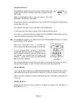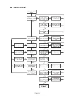
8.3.4 Boiler Connections
All connections to the appliance should be made with compression fittings.
8.3.5 Additional Requirements for a Kabin Pak Combi
1.
Although the Kabin Pak is manufactured from galvanised sheet it is recommended
that after a period of weathering (approx 4-8 weeks) that the Kabin Pak is painted with
a suitable primer and finish coat to prevent corrosion.
2.
When using the Kabin Pak with the integral low level flue only 28 second redwood
number 1 (kerosine) may be used in order to comply with building regulations. Suitable
flue terminal positions are shown on page 27.
3.
The boiler must be provided with a suitable well drained hard standing area to prevent
the formation of pools of water in order to eliminate any risk to the service engineer or
end user.
4.
The boiler must not be serviced or the panels removed where there is a risk of the
ingress off water.
5.
Although the Kabin Pak has been weatherproofed to IP45 it should not be subjected to
a jet of water from a hose or power washer.
8.3.6 Expansion Vessel
A 12 litre expansion vessel charged to 0.5 bar is supplied with the boiler. This can
accommodate a maximum system volume of approximately 150 litres.
If this volume
is exceeded an additional vessel will be required
. Refer to BS 7074: Part 1 or BS
5449 for details of sizing. The values given in the table are for total system values
which includes the primary water capacity. See page 4.
8.3.7 System Filling
As standard, a filling point complete with a filling loop has been included within the
appliance. The temporary hose must be disconnected after filling. A system pressure
when cold of 1 bar is recommended.
Water loss from the system as indicated by a reduction in pressure on the pressure
gauge may be made up through the filling loop.
After filling, vent all air from the system. Ensure the caps on the automatic air vents are
loose and bleed both circulating pumps.
VESSEL VOLUMES
0.5
2.1
4.2
6.3
8.3
10.5
12.5
14.6
16.7
18.7
20.8
22.9
25.0
1.0
2.7
5.4
8.2
10.9
13.6
16.3
19.1
21.8
24.5
27.2
30.0
32.7
1.5
3.9
7.8
11.7
15.6
19.5
23.4
27.3
31.2
35.1
39.0
42.9
46.8
25
50
75
100
125
150
175
200
225
250
275
300
INITIAL CHARGE
TOTAL
SYSTEM
VOLUME
Page 33


