OPTIONAL CONTROLS
TR05A140.B1107
55
7 OPTIONAL CONTROLS
7.1 External controls, programmers and room thermostats
All external controls used with this appliance MUST BE ZERO-VOLT SWITCHING ONLY!
If mains voltage, i.e. a switched live, is fed to the control terminals THE APPLIANCE WILL NOT
FUNCTION and could be SEVERELY DAMAGED!
7.1.1 Appliance connections
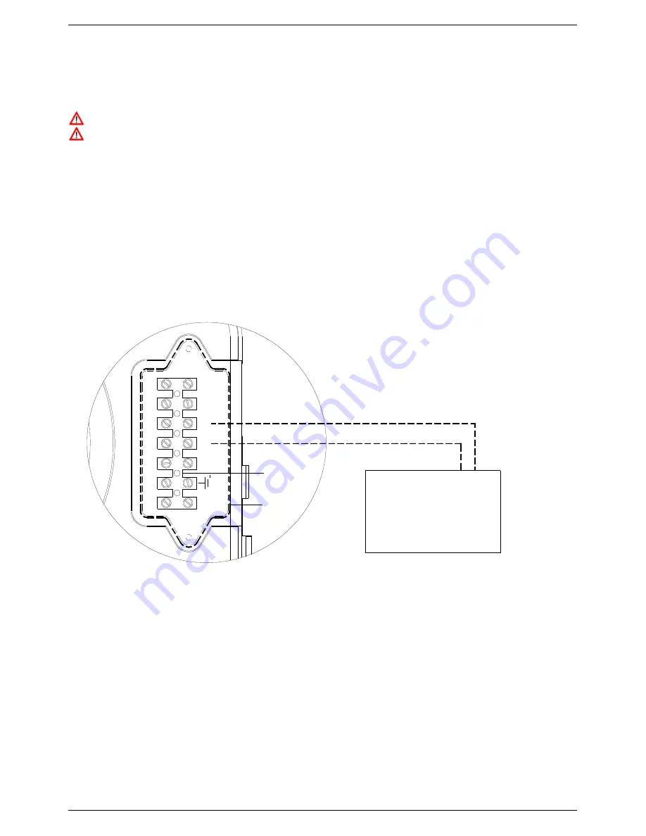
To fit a programmer, room thermostat or other external controls:
•
Isolate the electricity, water and gas supplies to the appliance;
•
Remove the front casing panel of the boiler (refer to 6.3 for guidance);
•
Remove terminal block cover
A
of the control panel;
•
Remove the link
between the two terminals marked
Ta
on terminal block
B
;
•
Connect the two wires from the programmer, room thermostat or controls to the terminals marked
Ta
;
•
Replace terminal block cover
A
.
External Controls:
- Room thermostat
- Programmer
A
- S-Plan system
S
e
S
e
T
a
N
L
B
T
a
Figure 52: Connection of external controls
Summary of Contents for GS25A
Page 2: ...TR05A140 B1107...
Page 59: ...THIS PAGE IS INTENTIONALLY BLANK THIS PAGE IS INTENTIONALLY BLANK...
Page 60: ...THIS PAGE IS INTENTIONALLY BLANK THIS PAGE IS INTENTIONALLY BLANK...
Page 64: ...THIS PAGE IS INTENTIONALLY BLANK THIS PAGE IS INTENTIONALLY BLANK...
Page 65: ...THIS PAGE IS INTENTIONALLY BLANK THIS PAGE IS INTENTIONALLY BLANK...


