Page 50
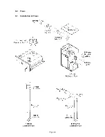
5.1.1 Installation of a Balanced Flue (FBF)
.
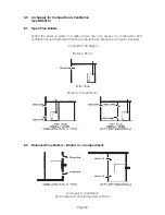
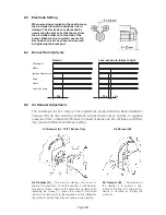
Make a suitable sized hole in the wall or ceiling for the flue. For the dimensions of
the boiler, see the Dimensions Section of this manual. For the dimensions of the flue
system, see the Flue Kits & Dimensions Section of this manual.
Note
: The cavities around the opening must be sealed and protected by a non-
combustible sleeve.
2.
Remove the top casing panel. If fitting a low level horizontal flue (FBF), remove the
upper casing panel knockout from the appropriate side or rear panel using a pair
of tin snips. Push the boiler into position against the wall then install the flue starter
piece, securing it in position using the nuts provided and ensuring the black rubber
gasket is correctly seated. The white fibre gasket supplied in the Flue Fittings Kit
(FFK) is not required and should NOT be fitted.
3.
If installing extension pieces, ensure the seals are correctly fitted and lubricated
before pushing through the wall and into the starter piece.
Note
: Refer to the Flue Options, Components and Dimensions Section for details of
the maximum number of extension pieces and total flue lengths allowed.
4.
If installing a vertical flue, correctly fit the flashing kit then slide the flue terminal into
position with a twisting movement. Ensure that the terminal protrudes through the
roof by a minimum of 665mm.
If installing a horizontal flue, slide the flue terminal into position with a twisting
movement then seal the gap between the flue and the wall both inside and outside.
Ensure that the terminal protrudes through the wall by a minimum of 75mm and a
maximum of 225mm.
If installing a Plume Management Kit, fit the starter piece and horizontal terminal as
described above then install the Plume Management Kit as instructed in the leaflet
supplied with the kit.”
5.
If installing a low-level horizontal flue, fit the terminal guard (basket) over the flue
terminal using the cardboard mounting template supplied with the flue kit to locate
and drill the necessary screw holes in the wall.
6.
Remove the air inlet cover from the burner then fit the intake adaptor spigot and
gasket. Connect one end of the air duct / hose to the flue and the other end to the
adaptor spigot and secure.
Summary of Contents for Kabin Pak Combi KC70HE
Page 51: ...Page 49 5 0 Flues 5 1 Installation of Flues...
Page 76: ...Page 74 Notes...
Page 77: ...Page 75 Notes...
Page 78: ...Page 76 Notes...

