300 min
Terminal
Assembly
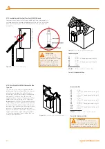
Top View Rear Flue
Property Boundary Line
*
N
I
I
G
F
M
I
A
A
F
H
J,K
D
E
H
C
R
A
I
J,K
I
L
S
B
T
U
Likely flue positions requiring
a flue terminal guard
Figure 32
Environmental locations of flue
Terminal Position with Minimum Distance
(mm)
A
1
Directly below an opening, air brick, opening windows, etc.
300
B
1
Above an opening, air brick, opening window etc.
300
C
1
Horizontally to an opening, air brick, opening window etc.
300
D
2
Below gutters, soil pipes or drain pipes.
25 (75)
E
2
Below eaves.
25 (200)
F
2
Below balconies or car port roof.
25 (200)
G
2
From a vertical drain pipe or soil pipe.
25 (150)
H
2
From an internal or external corner.
25 (300)
I
Above ground, roof or balcony level.
300
J
From a surface or boundary line facing a terminal.
600
Terminal Position with Minimum Distance
(mm)
K
From a terminal facing a terminal (Horizontal flue).
From a terminal facing a terminal (Vertical flue).
1200
600
L
From an opening in carport (e.g. door, window)
into the dwelling.
1200
M
Vertically from a terminal on the same wall.
1500
N
Horizontally from a terminal on the same wall.
300
R
From adjacent wall to flue (vertical only).
300
S
From an adjacent opening window (vertical only).
1000
T
Adjacent to windows or openings on pitched and flat roofs
600
U
Below windows or openings on pitched roofs
2000
1 In addition, the terminal should be no nearer than 150 mm to an opening in the building fabric formed for the purpose of accommodating a built-in element such as a window frame.
2 Only ONE 25mm clearance is allowed per installation. If one of the dimensions D, E, F, G or H is 25mm then the remainder MUST be as shown in brackets, in accordance with B.S.5440-1.
NOTE:
The distance from a
fanned draught appliance
terminal installed parallel to
a boundary may not be less
than 300 mm in accordance
with the diagram below
2.7.3. Peripheral Distances of Flue Output Connections
In order to position the flue set output pipe
2.7.4. Installation with Horizontal Flue Sets
Connecting Horizontal Homocentric Flue Set to the Combi, (original
diameter DN 60/100 mm)
Since your combi is hermetic model, it takes the used air from exterior and
discharges exhaust gases created as the result of burning through the same
flue group. In order to prevent emission of excessively harmful exhaust
gases, flue usage and installation is very important, therefore warnings
should be taken into consideration when flue connections are being
performed.
•
Make required flue selection for the flue connection to be made
externall and installation place of the combi. If the standard flue set
is not adequate, please select most suitable elements from our list of
connection accessories considering warnings given in our user's guide.
•
Fix the flange under the Bend piece (1) by using the Flange Bolt (10) via
Flange Connection Screws (11) to holes on the combi.
•
2 impermeability bolts within the hermetic flue set (2) are placed into
internal pipe slots at both ends of the 90° Bend.
•
Place the exterior wall (EPDM) bolt into the flue terminal as seen in
Figure 19 for grouping the flue output terminal. After placing the flue
output terminal through exterior of wall and the previously opened
hole, fix the Interior Wall Connection Bolt (7) into the flue terminal.
20
warmhaus.com


