16
warmhaus.co.uk
3.8. Filling Appliance & Adding Inhibitor
Fıllıng Loop Connectıon
When filling there may be a slight water leak from the air vent therefore
electrical connections should be protected.
ATTENTION
Do not adjust the system pressure if the boiler unit is hot, we suggest that
the boiler temperature is shown as below 40 degree's on the boiler display
screen before adjusting the pressure.
Ensure the system has been cleaned following the guidance of BS 7593 and
that all existing and installation debris is removed.
The primary heating circuit must not be filled with artificially or salt based
softened water it must be filled with an untreated cold supply from the
cold water main.
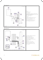
The filling loop must be WRAS approved and not be a permanent
installation (see below image)
If there is an additional expansion vessel fitted on the circuit, please ensure
the charge pressure is the same as the boiler vessel (0.75 bar).
If the filling loop is located away from the boiler then ensure a pressure
gauge is located next to the filling loop to ensure correct filling pressure.
The filling loop should always be removed, and suitable caps fitted to the
valves after filling the system has been carried out.
CH
RETURN
DHW
INLET
A
B
3/4 G"
1/2 G"
3/4 G"
1/2 G"
3/4 G"
CH FLOW
DHW OUTLET
GAS INLET
DHW INLET
CH RETURN
CH Return
Pipe Line
Check
Valve
Isolation
Valve
CH Return
Pipe Line
Closed
Closed
Open
Open
Isolation
Valve
Check
Valve
A
B
A
B
FILLING LOOP CONNECTION
TOP UP POSITION
A
B
0
1.5
bar
Manometer
Manometer
I. FILLING LOOP WITH FLEXIBLE HOSE
0
CH
RETURN
DHW
INLET
A
B
CH Return
Pipe Line
Check
Valve
Isolation
Valve
CH Return
Pipe Line
Closed
Closed
Open
Open
Isolation
Valve
Check
Valve
A
B
A
B
FILLING LOOP CONNECTION
TOP UP POSITION
A
B
0
1.5
bar
Manometer
Manometer
0
Filling Loop Connection
1. Remove the dust cap and connect to flexible hose to the check valve
securely.
2. Slowly turn the both valves to the Open position until the pressure
gauge reads between 1.2 and 1.5 bar.
3. Turn the both valves slowly to the Close position and check the pressure
in between 1.2 and 1.5 bar if pressure less than 1.2 bar then.
4. Slowly turn the both valves to the Open position until the pressure
gauge reads between 1.2 and 1.5 bar.
5. Turn the both valves slowly to the Close position and disconnected the
flexible hose from the check valve.
6. Fit the dust cap to the open and make sure no water leakage from valves
or caps.
NOTE:
If loss of pressure problem persists you must contact your installer
or service company.
Adding Inhibitor
CAUTION
The inhibitor used in the system with your Warmhaus boiler must not cause
damage to any materials within the boiler e.g. stainless steel, copper, brass
and any other composite material.
If the boiler is installed in areas such as leisure accommodation, then the
inhibitor must incorporate an anti-freeze solution or the anti-freeze solution
can be added separately but must be suitable for the boiler materials as
above.
We advise that the PH level of the system water should be between 6 -8
and any chemicals added must not change this.
When the inhibitor is added please record this with a label (if the inhibitor
manufacturer supplied this) or with a suitable method so that the
installation date can be monitored for service.
Inhibitor levels should be monitored and checked on service/maintenance
visits to confirm the system has the correct dosage.
Always add the specified dosage given by the inhibitor manufacturer and
Caution should be taken when disposing of all containers from the inhibitor
after installation.
If there is any doubt on the suitability of the inhibitor you wish to use then
please consult Warmhaus technical before adding to the system.
0034_00.DUK170726
0
0
34_0
0.DUK1
70
726
Summary of Contents for EWA 2525C
Page 1: ...CONDENSING COMBI BOILERS INSTALLATION SERVICE MANUAL EWA 2525C 25 kW EWA 2530C 30 kW...
Page 2: ......
Page 3: ...3 warmhaus co uk...
Page 57: ...57 warmhaus co uk...


