54
warmhaus.co.uk
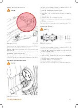
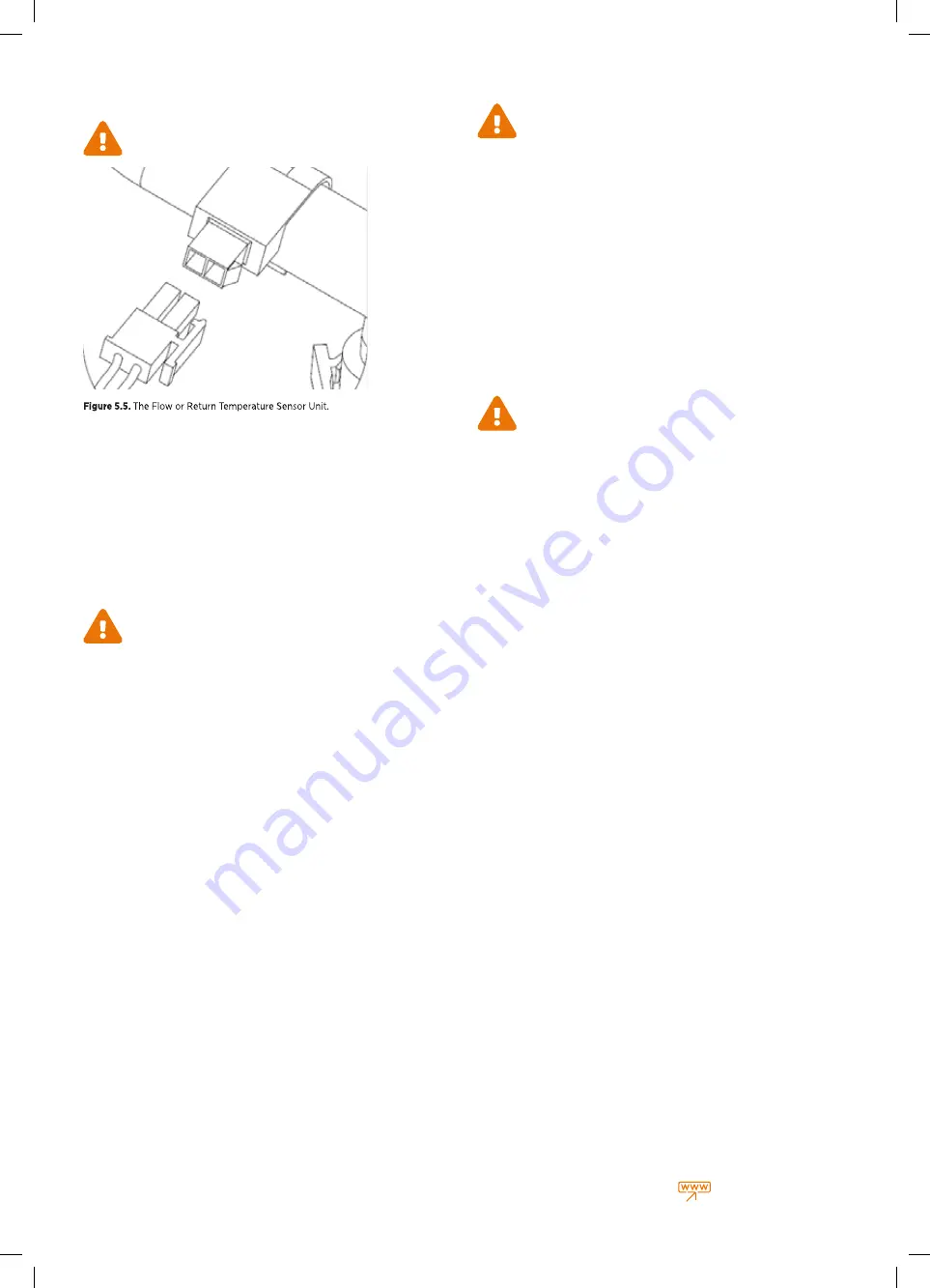
5.8. FLOW & RETURN TEMPERATURE SENSOR
Replacement
CAUTION
Please follow the steps listed in replacement of components FIRST STAGE
1. Disconnect the sensor lead from the flow or return thermistor unit.
2. Unclip and remove the flow or return thermistor from the pipe work and
withdraw the sensor from the boiler.
3. Re-fit the thermistor to the pipe work and ensure it is securely clipped
and in good contact with the pipe work and located into the locator tab.
4. Re-connect the thermistor lead to the thermistor.
Please follow the step listed in replacement of components FINAL STAGE.
5.9. Main PCB Replacement
CAUTION
Please follow the steps listed in replacement of components – FIRST STAGE
1. Carefully remove the 8 retaining clips and remove the control box cover.
2. Remove the 2 screws that secure the PCB.
3. Gently spread the two side retaining clips and lift the PCB upwards
ensuring it clears the four corner locating posts.
4. Unplug all electrical connections from the PCB and make a note of where
each connection is located (wiring diagram can be used in reference for
connection locations)
5. If the EEPROM on the existing PCB is in good working order it maybe
be transferred to the new PCB, however the following checks must be
carried out to ensure they match the default settings in the parameter
list.
6. Check P15 value on the parameter list
7. Check P22 value on the parameter list
8. Check P44 value on the parameter list
9. Check P46 value on the parameter list
10. If you wish to use the new EEPROM supplied with the new PCB then the
above checks must also be carried out.
11. Re-connect all electrical connections to the PCB ensuring they are
connected correctly.
12. Install the PCB in reverse order as the above instructions 3,2,1.
13. When power is restored to the boiler and a new EEPROM has been used
the boiler LCD will display E62 error code.
14. To clear the error code you must run Auto Calibration.
Please follow the step listed in replacement of components FINAL STAGE.
5.10. 3-Way Inner Kit Replacement - TOP
CAUTION
Please follow the steps listed in replacement of components – FIRST STAGE
1. Refer to the Draining the Boiler CH circuit section
2. Remove the diverter valve actuator and place safely within the boiler.
3. Unscrew the top brass connection nut and withdraw the 3 way valve
inner cartridge upwards and out of the boiler.
4. Ensure the brass manifold is clean.
5. Screw the new 3 way valve inner cartridge into the brass manifold
ensuring the spindle connects and fits into the bottom O-ring, tighten
the cartridge.
6. Re-pressurize the boiler and bleed all excess air.
7. Re-connect the diverter valve actuator.
Please follow the step listed in replacement of components FINAL STAGE.
5.11. Pump Head Replacement
CAUTION
Please follow the steps listed in replacement of components – FIRST STAGE
1. Refer to the Draining the Boiler CH circuit section.
2. Disconnect the electrical connector plugs from the pump.
3. Remove the 4 x screws securing the pump head.
4. Remove the pump head and ensure the pump head housing is clean.
5. Install the new pump head and secure the 4 x pump head securing
screws.
6. Reconnect the electrical connector plugs to the pump.
7. Re-pressurize the boiler and bleed all excess air.
Please follow the step listed in replacement of components FINAL STAGE.
0086_00.W210424
Summary of Contents for EWA 2525C
Page 1: ...CONDENSING COMBI BOILERS INSTALLATION SERVICE MANUAL EWA 2525C 25 kW EWA 2530C 30 kW...
Page 2: ......
Page 3: ...3 warmhaus co uk...
Page 57: ...57 warmhaus co uk...


