23
warmhaus.com
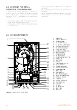
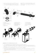
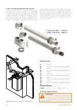
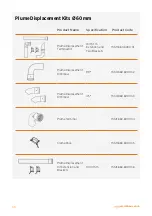
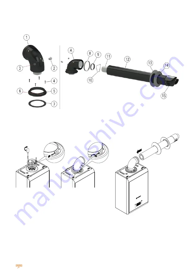
1. 90° elbow
2. Inspection Cap (Gas)
3. Inspection Cap (Fresh Air)
4. Screws
5. Flange Gasket
6. Flange Gasket Screw
7. Neoprene Gasket
8. Ø100 Sealing Gasket
9. Ø60 Sealing Gasket
10. Centralizer
11. Internal Flue Pipe
12. Internal Flue Pipe
13. Internal Wall Plate
14. External Wall Plate
15. Grill
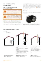
Figure 33
Hermetic combi boiler concentric flue set.
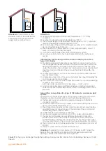
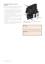
• Loosen the Flange Gasket Screw (Fig.33_6) and remove it from the elbow (Fig.33_1)
• Put the Neoprene Sealing Gasket (Fig.33_7) under the flange and secure it with 4 screws (Fig.33_6 and see Picture A)
• Place the flue elbow (90°) (Fig.33_1) press down and tighten the screw (Fig.33_6) to secure the flue elbow (see
picture B )
• Fit the outer and inner wall flanges (Fig.33_13-14) on the terminal pipe (Fig.33_12)
• Connect flue to the boiler, positioning the seals correctly (picture C). Seal the flue into the wall with silicone or sand +
cement and cover with Wall Seals provided.
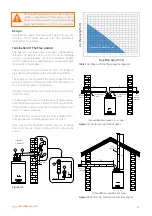
• It is important that the flue terminal must have an horizontal sloping not less than 1,5 deg. (25 mm per meter) towards
the boiler.
A
Picture A
Picture B
Picture C
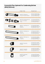
• Make required flue selection for the flue connection
to be made external and installation place of the
combi boiler. If the standard flue set is not adequate,
please select most suitable elements from our list of
connection accessories considering warnings given in
our user's guide.


