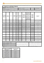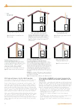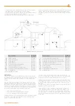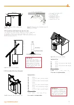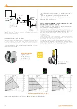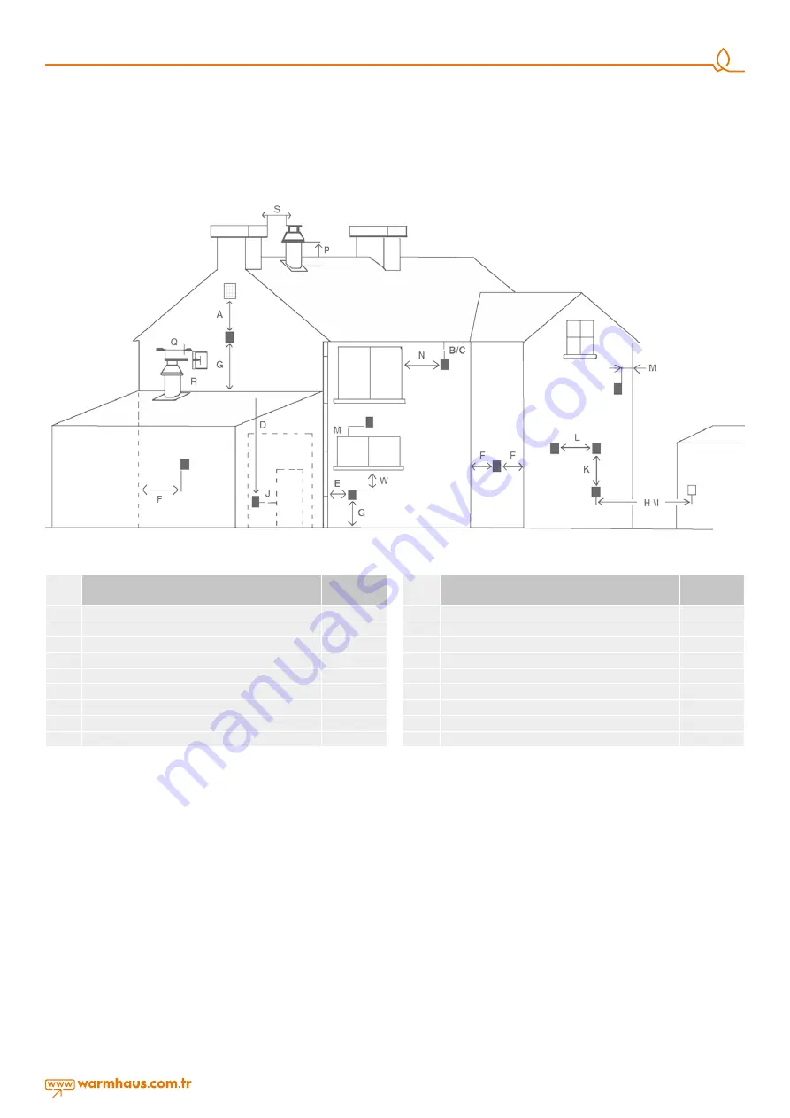
Figure 16
Environmental locations of flue
Flue Location
Minimum
Distance
A
Under a window
300 mm.
B
Under water groove
75 mm.
C
Under fringes
200 mm.
W
Under balcony
200 mm.
E
To vertical water discharge pipes
150 mm.
F
Interior or exterior corners
300 mm.
G
On the ground, roof or balcony level
300 mm.
H(*)
On another wall corresponding to the flue
600 mm.
S
To another flue
1200 mm.
(*) Not recommended for C5 and C6
Flue Location
Minimum
Distance
J
To a door other than garage wall
1200 mm.
R
To another flue from the same wall (vertical)
1500 mm.
Q
To another flue from the same wall (horizontal)
300 mm.
M
On another window/manhole
300 mm.
N
On another window/manhole horizontally
300 mm.
P
On the roof level
300 mm.
F
To an adjacent wall
300 mm.
I(*)
To the window on adjacent wall
1000 mm.
L
To another flue
600 mm.
VENTILATION
“Viwa 50 -65” boilers an be installed in boiler rooms whose size and
requirements meet current regulations. The following is provide for your
guidance only, and assumes the ventilation air is taken directly from
outside.
The sizes of the vents may need to be increased inrespect of other
appliances installed in the same area, and seasonal use. Take care that
the position of low level vents would not subject to adverse weather
conditions, ie flooding. Ventilation requirements for Viwa 50 -65 boilers
and cascade systems. BS6644 has a requirement that the temperatures
in a room or compartment do not exceed certain levels:
-
+25°C at floor level (0-100 mm)
-
+32°C at mid level (1.5 m above the floor level)
-
+40°C at ceiling level (0-100 mm from ceiling)
When installed as a class B appliance (open flued, not roomed sealed).
Installed in a room High level (within 15% of the room height from
ceiling) - 2 cm²/kW of net heat input
Low level (low as possible within 1 meter from floor natural gas ) - 4
cm²/kW of net heat input a single Viwa 50 (46.88 KW net input) boiler
would require 100 cm² at high level and 200 cm² at low level.
Installed in a compartment or enclosure High level (within 15% of the
room height from ceiling) - 5 cm²/kW of net heat input Low level (low
as possible within 1 meter from floor natural gas) - 10cm²/kW of net
heat input.
A single Viwa 50 (46.88 KW net input) boiler would require 250 cm² at
high level and 500 cm² at low level.
When installed as a class C appliance (room sealed). Installed in a
room High level (within 15% of the room height from ceiling) - 2 cm²/
kW of net heat input Low level (low as possible within 1 meter from
floor natural gas) - 2 cm²/kW of net heat input A single Viwa 50 (46.88
kW net input) boiler would require 100 cm² at high level and 100 cm²
at low level.
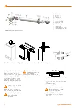
• 2 impermeability bolts within the hermetic flue set (2) are placed
into internal pipe slots at both ends of the 90° Bend.
• Place the exterior wall (EPDM) bolt into the flue terminal as seen in
Figure 11a for grouping the flue outlet terminal.
After placing the flue outlet terminal through exterior of wall and the
previously drilled hole, fix the Interior Wall Connection Bolt (7) into the flue
terminal. Place the other end of EPDM connection bolt installed on 90°
flue bend of your boiler to the flue outlet. Ensure that sealings are placed
properly:
11


