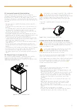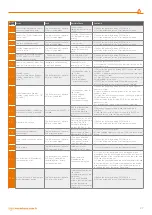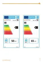
Figure 41
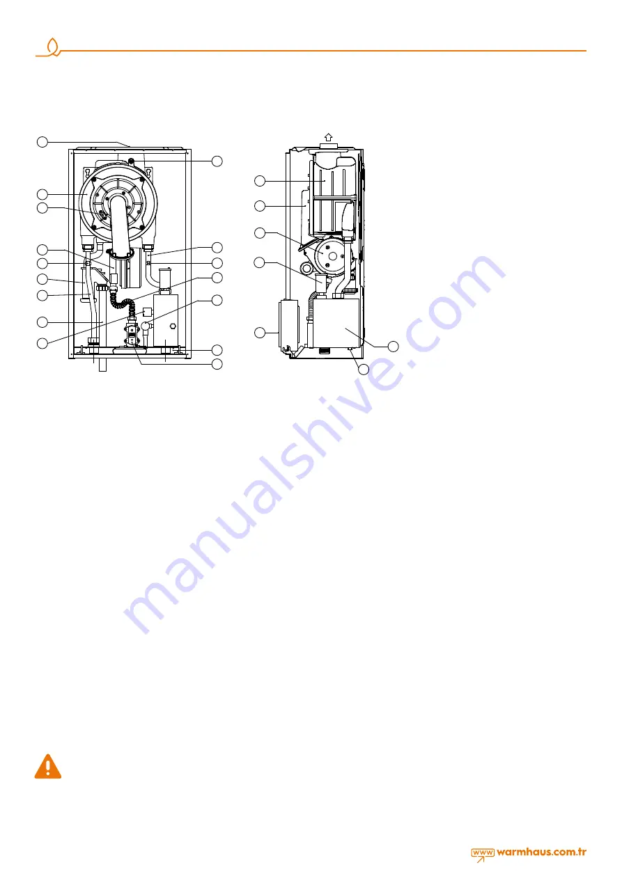
Components of the Boiler
1. Flue Outlet
2. Main Exchanger
3. Ignition Electrode
4. Air-Gas Mixture Unit (AGM)
5. Heating Supply NTC Sensor
6. Condensation Water Flusher
7. Heating Supply Pipe
8. Condensate Water Drainage Hose
9. Low Water Pressure Probe
10. Flue Gas NTC Sensor
11. Gas Supply Pipe
12. Heating Return NTC Sensor
13. 4 bar Safety Valve
14. Manometer
15. Gas Valve
16. Exchanger Cover
17. Electronic Fan
18. Automatic Air Purger
19. Control Panel
22 Heating Return Pipe
21 Strainer Drainage
22 CH Intake Dirt and Air Collector
2.3.1. Components of the Boiler
3. FOR USERS
3.1. GENERAL WARNINGS FOR USERS
3.1.1. Use of the Boiler
If you sense gas odor, first close the gas valves of the boiler and gas
intake line of your house or valves of LPG (LNG) tanks if you use bulk
gas. Do not turn on-off electricity switches, and do not do anything that
may generate sparks. Call gas company or authorized service (See 1.3
Gas leaks)
Start-up of your boiler must be carried out by Warmhaus Authorized
service in order to maintain warranty scope of your boiler. After our
Authorized Service have carried out start-up checks and started your
boiler, they shall inform you about use of the boiler.
Carry out the following checks prior to use:
•
Ensure that; radiator/heating system and gas valves under the boiler
are open,
•
The heating system pressure read on the manometer under the
boiler is between 1 - 1,5 bar, and system air has been purged, boiler
valves are open if there is a boiler connection in the system,
•
There is gas in your gas supply line (you can check by turning on
one of the gas burning appliances),
•
Electrical switch of the boiler is turned on,
•
There are not any flammable materials or products near the boiler,
•
The exhaust gas flue set is not blocked,
•
Room thermostat(s) or control device is at ON position (if
applicable).
•
Follow the procedure given below if you are not going to use, and
shut down the boiler in winter season with frost conditions:
•
Drain the heating system water which does not contain
antifreeze.
•
Turn off the electrical switch, gas valve of the boiler, heating
and domestic hot water!
Follow the steps given below if you are going to turn off the boiler for
a short term:
•
Do not turn off the electrical switch, gas valve of the boiler, heating
and domestic hot water!
•
Leave the boiler in Stand-by (OFF on the display) position, thus Anti-
Frost Function will be enabled.
Turn off the boiler during maintenance and repair operations near
the exhaust gas discharge flues. Have your boiler checked by
Warmhaus Authorized Service prior to turning on the boiler after such
maintenance.
Follow the rules specified below:
•
Do not clean the outer body of the boiler while the boiler is
operating, and do not use flammable materials for cleaning.
•
Do not touch the boiler with wet hands or feet; or with bare hand or
without footwear.
•
Do not pull electrical cables.
•
If the cables are damaged, turn of the boiler and switches, and do
not use the boiler!
•
Electrical cables of the boiler and its accessories shall be replaced
only by the Authorized Service.
•
Do not expose the mounted boiler to any vapors resulting from
cooking.
•
Prevent use of the boiler by children and unexperienced persons.
3.2. SELECTION OF ON / OFF / STAND-BY AND
SUMMER / WINTER MODES
Use V circuit breaker (switch) to disconnect the boiler from power
supply. When the appliance is energized, heating temperature on the
left-hand side of the screen and hot domestic water temperature (if
an HDW boiler is fitted) on the right-hand side of the screen shall be
displayed.
3.2.1. On/Off/Stand-by Positions
Use V circuit breaker (switch) to turn on/off power supply connection of
the boiler.
2
4
6
7
9
11
13
17
16
2
19
12
14
1
10
3
5
8
15
1 Flue Outlet
2 Main Heat Exchanger
3 Đgnition Electrode
4 Air gas Mixing Unit (AGM)
5 CH NTC Sensor
6 Condensation Water Trap (Siphon)
7 Radiator Outlet (Flow) Pipe
8 Condensation water Discharge Hose
9 Low Pressure switch
10 Flue Gas NTC Sensor
11 Gas Inlet Pipe
12 CH Return NTC Sensor
13 4 Bar safety Valve
14 Manometer
15 Gas valve
16 Heat Exchanger Door
17 Electronic Fan
18 Automatic air relief Valve
19 Control Panel
20 Radiator Inlet (Return) Pipe
21 Dirt Collector Drain
22 CH Inlet Dirt & Air Collector
20
1 Baca Çıkıı
2 Ana Eanjör
3 Ateleme Elektrotu
4 Hava gaz Karıım Ünitesi (AGM)
5 Kalorifer Gidi NTC Sensörü
6 Yoğuma Suyu Sifonu
7 Kalorifer Gidi Borusu
8 Yoğuma Suyu Tahliye Hortumu
9 Düük Su Basınç Anahtarı
10 Baca gazı NTC Sensörü
11 Gaz Giri Borusu
12 Kalorifer Dönü NTC Sensör
13 4 Bar Emniyet Ventili
14 Manometre
15 Gaz Valfi
16 Eanjör Kapağı
17 Elekronik Fan
18 Otomatik Hava Purjörü
19 Kumanda Paneli
20 Kalorifer Dönü Borusu
21 Kir Toplayıcı Drenaj
22 CH Giri kir ve hava kolektörü
21
4 Bar
18
22
22

