Main
Electric
Panel
Boiler Pump
Panel - Relay
Connection
3 x 1.0 mm
2
Outdoor Sensor
2 x 1.0 mm
2
1. Zone + Storage Tank
Timer / Room Thermostad
Timer / Room Thermostad
2 x 1.0 mm
2
Boiler Pump
3 x 1.0 mm
2
3-Way Motorized
Valve Line
3 x 1.0 mm
2
In this electric scheme,
the boiler pump and
the system pump will be
managed via main electric
panel contactor.
COLD WATER
COLD WATER
RE
CIRCUL
ATION CIRCUIT
Boiler Sensor
2 x 1.0 mm
2
System Pump Boiler Panel
Relay Connection
The recirculation pump
will not be managed
by Boiler. It will be
managed by the main
electric panel.
Recirculation Pump
GAS
PIPELINE
Pump Cable
3 x 1.0 mm
2
FLUE
2.1.5. Natural Gas Connection (Appliance Category I
2H
)
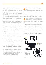
The boilers are designed to run on methane (G20) gas. Gas supply
pipes shall be equal to or larger than 3/4"G boiler fittings. Prior to
making the gas connection, a thorough internal cleaning shall be
carried out to all fuel supply installation pipe furnishings as possible
wastes may distort smooth operation and reliability of the boiler.
Ensure that the gas supplied by the mains line is of the type prescribed
for the boiler (refer to the label on the boiler).
Also, in case of reduced pressure, the network dynamic pressure
(methane or LPG) used for supplying the combi should be carefully
controlled and will impact the boiler strength. Ensure that gas valve
connection is correct. Flammable gas supply pipe should be able to
supply correct adequate gas amount to the boiler when the boiler is
at full power and be projected and sized according to force and local
gas company specification and instructions in order to guarantee the
appliance efficiency. Connection system shall comply with the legislation
in force.
2.1.6. Flammable Gas Quality
The boiler is designed to be used with pure fuel not containing any
foreign substances; therefore, required filter systems must be available in
the gas supply line (for ensuring purification of the fuel).
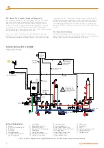
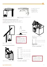
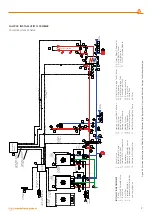
Figure 7 Viwa 50-65 Single Boiler with 1 High Temperature Zone + Hot Water Storage Tank System Scheme Example.
INSTALLATION EQUIPMENT
1. Boiler
2. Gas Safety Solenoid Valve
3. Ball Valve
4. Gas Filter
5. Vibration Isolator
6. Condensate Water Siphon
and Drainage Line
7. Check-Valve
8. Boiler (Return) Pump
9. Automatic Air Vent
1O. Sediment-Dirt-Air Separator
11. Manometer
13. Hydraulic Separator
14. Sediment-Dirt-Separator
17. Heating System Pump
18. Heating System
19. Pressure Reducer
20. Hot Water Storage Tank
22. Hot Water Storage Tank Sensor
23. Air Separator
24. Hot Water Storage Tank
Recirculation Circuit
25. Recirculation Pump
26. Safety valve
27. Vessel Tank
28. Filter
29. Timer / Room Thermostat
30. Main Electric Panel
31. Outside Sensor
SAMPLE INSTALLATION SCHEME
Single Boiler Scheme
8


