21
CP: Min Ø 19 mm
CP: Min Ø 19 mm
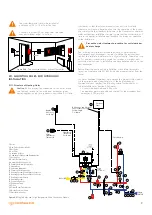
Drainage and Ventilation Pipe
≥ 100
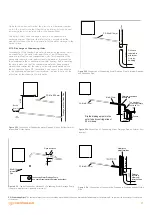
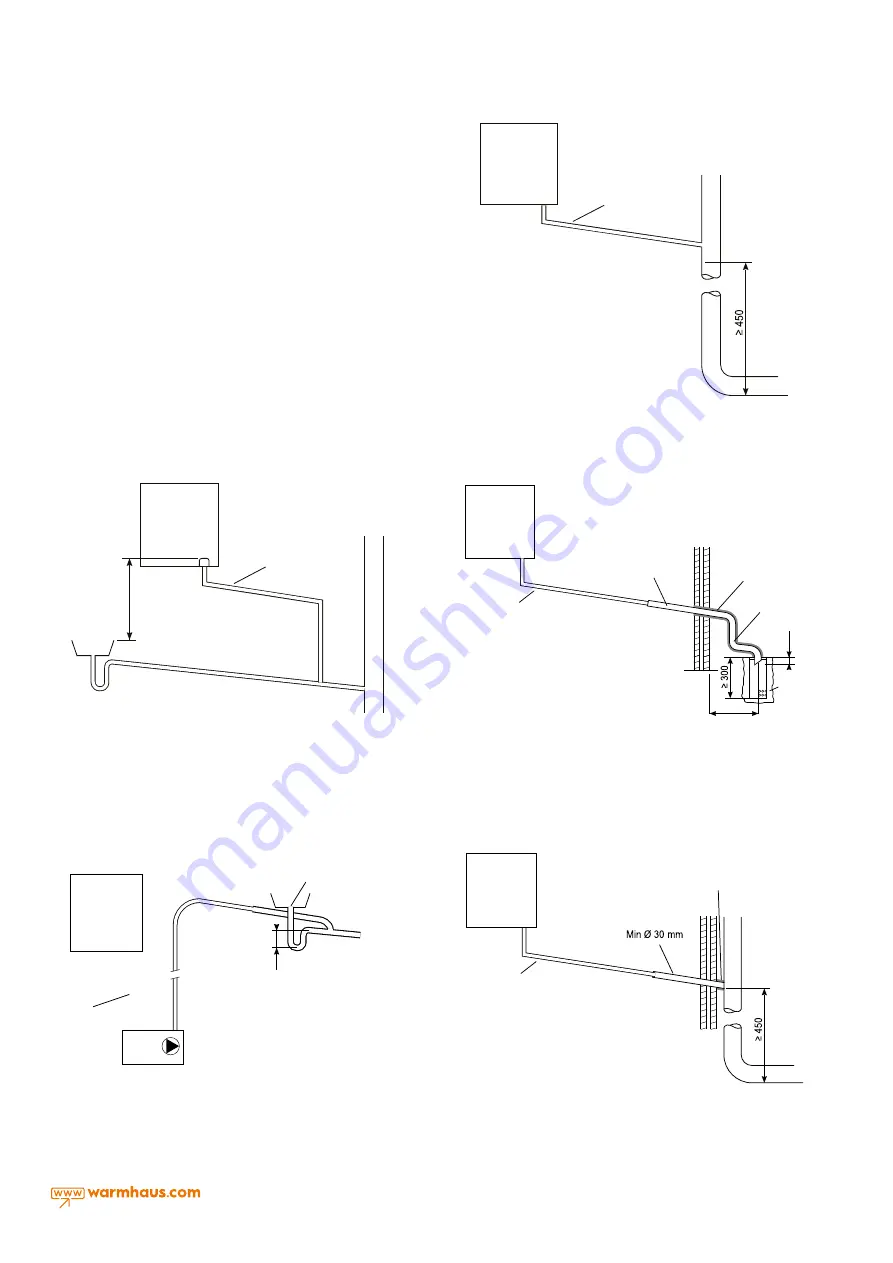
Figure 2.23
Connection of Condensate Drainage Pipe to
Internal Soil & Vent Stack
Figure 2.24
Connection of a Condensate Drainage Pipe
Downstream of a Sink, Basin, Bath or Shower Water Trap to
Internal Soil Vent Stack
Distance
required in
minimum
3-storey
building
Bath/s
hower
outlet
Drainage and Ventilation Pipe
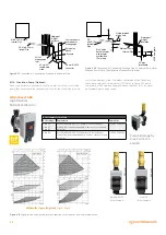
Figure 2.32
Connection of Condensing Water Drainage Pipe to Internal Drainage
and Ventilation Pipe
CP: Min Ø 19 mm
CP: Min Ø 19 mm
Drainage and Ventilation Pipe
≥ 100
Figure 2.23
Connection of Condensate Drainage Pipe to
Internal Soil & Vent Stack
Figure 2.24
Connection of a Condensate Drainage Pipe
Downstream of a Sink, Basin, Bath or Shower Water Trap to
Internal Soil Vent Stack
Distance
required in
minimum
3-storey
building
Bath/s
hower
outlet
Drainage and Ventilation Pipe
Figure 2.33
Connection of Condensing Water Drainage Pipe to Bottom Level of
Interior Bath Outlet Siphon
27
Installation and Servicing
SECTION 2 - INSTALLATION
Open air siphon
Condensing Water Drainage Pump
(see pump manufacturer's detailed instructions)
Min Ø 19 mm
Internal
Pipe
75
Min Ø 19 mm
Internal Pipe
CP: Min Ø 30 mm
Internal Pipe
Air space
Combined waste
and rainwater
drainage pipe
43 mm 90º
female/male
elbow
Waterproof
/ Airtight
insulation
68 mm Ø PVCU
Connector
CP: Min Ø 19 mm
Min Ø 30 mm
Water and Air insulated
drainage pipe
The maximum
outside pipe length
should be 3 m.
Dip the drainage pipe into the
outer tube by centring at least
25 mm deep.
Pebble
≥ 500
≥ 25
Distance
required in
minimum 3-
storey building
Drainage and Ventilation Pipe
CP: Min Ø 19 mm
Waterproof /
Airtight insulation
Visible air break
at plug hole
CP:
Min Ø 19 mm
Internal
Pipe
Sink, basin,
bath or shower
with integral
overflow and
75mm trap
Minimum 30 mm
Internal Pipe
Waterproof /
Airtight
insulation
≥ 25 Below grate
45º pipe
termination
75
≥ 100
Figure 2.25
Connection of a Condensate Pump Typical
Method (see manufacturers detailed instructions)
Figure 2.26
Connection of condensate Drainage Pipe to
External Soil & Vent Stack
Figure 2.27
Connection of a Condensate Drainage Pipe to an
External Rainwater Downpipe (only combined foul/rainwater
drain)
Figure 2.29
Connection of a Condensate Drainage Pipe to an
External Purpose Made Soak Away.
Figure 2.28
Connection of Condensate Drainage Pipe
Upstream of a Sink, Basin, Bath or Shower Waste Trap to
External Drain, Gulley or Rainwater Hopper
INS
T
ALL
A
TION
CONDENSATE............ CONT’D
45º cut
drainage pipe
inlet
External air
siphon
Figure 2.34
Connection of Condensing Water Drainage Pipe on Exterior Envi-
ronment
27
Installation and Servicing
SECTION 2 - INSTALLATION
Open air siphon
Condensing Water Drainage Pump
(see pump manufacturer's detailed instructions)
Min Ø 19 mm
Internal
Pipe
75
Min Ø 19 mm
Internal Pipe
CP: Min Ø 30 mm
Internal Pipe
Air space
Combined waste
and rainwater
drainage pipe
43 mm 90º
female/male
elbow
Waterproof
/ Airtight
insulation
68 mm Ø PVCU
Connector
CP: Min Ø 19 mm
Min Ø 30 mm
Water and Air insulated
drainage pipe
The maximum
outside pipe length
should be 3 m.
Dip the drainage pipe into the
outer tube by centring at least
25 mm deep.
Pebble
≥ 500
≥ 25
Distance
required in
minimum 3-
storey building
Drainage and Ventilation Pipe
CP: Min Ø 19 mm
Waterproof /
Airtight insulation
Visible air break
at plug hole
CP:
Min Ø 19 mm
Internal
Pipe
Sink, basin,
bath or shower
with integral
overflow and
75mm trap
Minimum 30 mm
Internal Pipe
Waterproof /
Airtight
insulation
≥ 25 Below grate
45º pipe
termination
75
≥ 100
Figure 2.25
Connection of a Condensate Pump Typical
Method (see manufacturers detailed instructions)
Figure 2.26
Connection of condensate Drainage Pipe to
External Soil & Vent Stack
Figure 2.27
Connection of a Condensate Drainage Pipe to an
External Rainwater Downpipe (only combined foul/rainwater
drain)
Figure 2.29
Connection of a Condensate Drainage Pipe to an
External Purpose Made Soak Away.
Figure 2.28
Connection of Condensate Drainage Pipe
Upstream of a Sink, Basin, Bath or Shower Waste Trap to
External Drain, Gulley or Rainwater Hopper
INS
T
ALL
A
TION
CONDENSATE............ CONT’D
45º cut
drainage pipe
inlet
External air
siphon
Figure 2.35
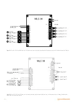
Typical Connection Method of a Condensing Water Drainage Pump
(see pump manufacturer's detailed instructions)
27
Installation and Servicing
SECTION 2 - INSTALLATION
Open air siphon
Condensing Water Drainage Pump
(see pump manufacturer's detailed instructions)
Min Ø 19 mm
Internal
Pipe
75
Min Ø 19 mm
Internal Pipe
CP: Min Ø 30 mm
Internal Pipe
Air space
Combined waste
and rainwater
drainage pipe
43 mm 90º
female/male
elbow
Waterproof
/ Airtight
insulation
68 mm Ø PVCU
Connector
CP: Min Ø 19 mm
Min Ø 30 mm
Water and Air insulated
drainage pipe
The maximum
outside pipe length
should be 3 m.
Dip the drainage pipe into the
outer tube by centring at least
25 mm deep.
Pebble
≥ 500
≥ 25
Distance
required in
minimum 3-
storey building
Drainage and Ventilation Pipe
CP: Min Ø 19 mm
Waterproof /
Airtight insulation
Visible air break
at plug hole
CP:
Min Ø 19 mm
Internal
Pipe
Sink, basin,
bath or shower
with integral
overflow and
75mm trap
Minimum 30 mm
Internal Pipe
Waterproof /
Airtight
insulation
≥ 25 Below grate
45º pipe
termination
75
≥ 100
Figure 2.25
Connection of a Condensate Pump Typical
Method (see manufacturers detailed instructions)
Figure 2.26
Connection of condensate Drainage Pipe to
External Soil & Vent Stack
Figure 2.27
Connection of a Condensate Drainage Pipe to an
External Rainwater Downpipe (only combined foul/rainwater
drain)
Figure 2.29
Connection of a Condensate Drainage Pipe to an
External Purpose Made Soak Away.
Figure 2.28
Connection of Condensate Drainage Pipe
Upstream of a Sink, Basin, Bath or Shower Waste Trap to
External Drain, Gulley or Rainwater Hopper
INS
T
ALL
A
TION
CONDENSATE............ CONT’D
45º cut
drainage pipe
inlet
External air
siphon
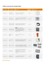
Figure 2.36
Connection of Condensation Drainage to Drainage and Ventilation
Pipe
CP (Condensing Pipe):
The horizontal pipe connections should be assembled as to have an downwards. Inclination must be minimum 3° as to allow the non-return of condensate
to the device.
Open this valve and ensure that the pressure in Manometer reaches
up to 1-1.5 bar and close the Filling Valve by turning it clockwise and
redischarge the air of radiators with air discharging valves.
The boiler’s safety valve discharge needs to be connected to a
discharge hopper. Otherwise, the safety valve is activated and the
manufacturer cannot be held responsible for the water drainage to the
device’s place.
2.11.3. Discharge of Condensing Water
For discharge of the condensation water generated by the device, it must
be connected to the waste water network via at least Ø19mm pipes
which are resistant to acidic condensation water. The connection of the
device with the waste water network should be made as to prevent the
liquid contained in the connection system from freezing. Before operating
the device, make sure that the condensation water has been properly
drained; then confirm that the siphon is filled with condensation before
the first operation (Figure 2.10). In addition, it is necessary to pay attention
to the applicable national and local regulations, in order to carry out the
instructions for the discharge of waste water.


