9
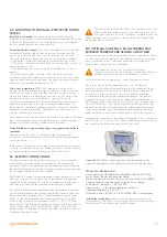
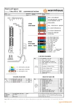
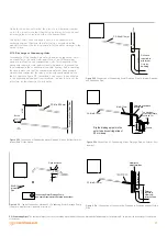
Figure 2.8
Environmental locations of flue
Chimney Position
Minimum
Distance
A
Under a window
300 mm.
B
Under water groove 75 mm.
75 mm.
C
Under fringes 20 mm.
200 mm.
W
Under balcony
200 mm.
E
To vertical water discharge pipes
150 mm.
F
To inside or outside corners
300 mm.
G
To ground, roof or balcony level
300 mm.
H (*)
To another wall corresponding to the wall
600 mm.
S
To another chimney
1200 mm.
J
From the garage wall to another door
1200 mm.
R
From same wall to another chimney (vertically)
1500 mm.
Q
From same wall to another chimney (horizontally) 300 mm.
M
On another window / culvert
300 mm.
N
Horizontally another window / culvert
300 mm.
P
To the roof level
300 mm.
F
To a neighbouring wall
300 mm.
I (*)
On the window on the neighbouring wall
1000 mm.
L
To another chimney
600 mm.
(*) Not recommended for C
5
ve C
6
!
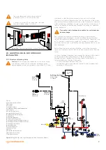
• The hanger plate supplied as standard with the boiler shall be
mounted on a full or half-full brick wall in accordance with the
connection screws and mounting template in compliance with its
technique and shall not be used for any other purpose.
• If different materials are used for mounting, the boiler will be out of
warranty.
• If the wall to be mounted on is not a brick wall, the durableness of
the support system must first be checked.
• The boiler must be mounted on a fire-resistant wall.
• It is recommended to mount the boiler between 1.8 - 2.2 m length
of hanger plate from the ground.
• In places where mounting area is limited, the boiler must be
mounted minimum 30 cm above the ground, with a space of
minimum 5 cm from the sides and 90cm from the front for easy
intervention of service technician.
• The boiler is not mounted in places with explosive, flammable
material and acid vapor.
• It is not mounted on sides of above cookers, ovens or heating
devices.
• Hermetic boilers can be mounted inside the furniture as well, but at
least 5 cm spacing should be left on their sides.
• It is advisable to connect the outlet of the boiler to the outlet line
by means of a transparent hose to prevent the possibility of water
coming from safety valve of boiler after mounting. If this is not
possible; do not put electronic devices, tools, parts and equipment
that can breakdown, rust, etc. under the boiler.
• Due to the above reasons, it is not recommended to put any
furniture under the boiler.
2.3.4. Air Supply, Ventilation and Flue Terminal Positioning Quick
Reference Guide for; BS 6644:2011, IGE/UP/10 (ed4) 2014 & BS
5440-1:2008, BS 5440-2:2009, BS6644:2011 Specification for the
Installation of gas-fired hot water boilers of rated inputs between
70 kW (net) and 1.8 MW (net) (2nd and 3rd family gases) & IGE/
UP/10 2014 Edition 4 Installation of Gas Appliances in Industrial
and Commercial Premises
For BS 6644 and IGE UP 10 Installations the ventilation openings might
need to be increased if the following air temperatures are exceeded.
(@15°C Ambient)
High-Level (100mm Below Ceiling Level)
40°C
Mid-level (1500mm Flow Floor Level)
32°C
Low-Level (100mm Above Floor Level)
25°C
As a guide, reduction of air temperature may be achieved by increasing
the inlet and outlet air supply by 0.15 m
3
/h or 0.2 cm
2
/kW of net heat
input per 0C of temperature reduction required.


