7 October 2021
Due to continued product improvement, Warmington Ind LTD reserves the right to change product specifications without prior notification.
All Dimension are in mm
………….
Copyright ©
22
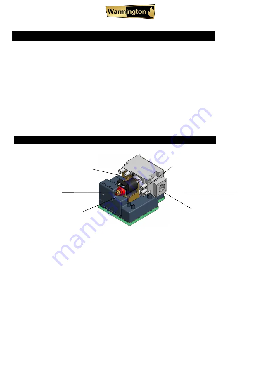
EG HI/LOW (SIT 843 valve)
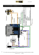
DIAGRAM B ( SHOWING CONTROL VALVE WITH TEST POINTS AND ADJUSTING SCREW )
•
After checking the pressure, turn the unit off, remove manometer from the test point and tighten the test point screw. Ensure
to check for gas leaks.
•
Ensure power is off & reconnect Modulator Harness Connection in the Main Harness. See Diagram B above.
•
Turn the appliance on and off a few times to check ignition.
•
When satisfied that the appliance is working correctly, fit the front panel assembly back to the gas burner.
•
NOTE : Ensure you peel the Protective Plastic Coating from any stainless steel components if fitted.
•
All burner Aerations are factory preset and cannot be adjusted.
•
If you are unable to get the unit to operate correctly, refer to troubleshooting before contacting your Local Service Contact.
•
It may take approximately 2 hours of operation for the coals/logs or river rocks to achieve their full flame pattern and glow.
•
During the initial burn period, some smoke and smell may be experienced. Because of this, run the appliance on the high po-
sition in a well ventilated room until fumes dissipate.
test point inlet
HI / LOW Harness Connections
test point outlet
1/2”
BSPT Gas outlet
SIT 843 Control Valve
Nut A
High setting adjustment screw
Screw B
Low setting adjustment screw
•
Light appliance and check the pressure to the hi kPa value in the table for maximum output.
NOTE : Any alterations to pressure is to be carried out by a Certified Gas Fitter.
•
If adjustments are necessary, remove the dust cap on the control value. The pressure adjustment
screw is on the front side of the gas control valve (shown in Diagram
B
in this specification) and is
factory
set.
WARNING:
Ensure that the dust cap is replaced after adjustment.
Pressure Setting
: Turn the burner on with the switch and wait for full ignition. Using a standard screw driver,
screw the adjusting screw clockwise to increase the outlet pressure, or screw counter clockwise to decrease
the pressure to the desired settings.
Set the pressure to the hi kPa value in the table for maximum output.
The burner will operate any pressure between the hi and the low pressures.


