


5 April 2019
Due to continued product improvement, Warmington Ind LTD reserves the right to change product specifications without prior notification.
All Dimension are in mm
………….
Copyright ©
4
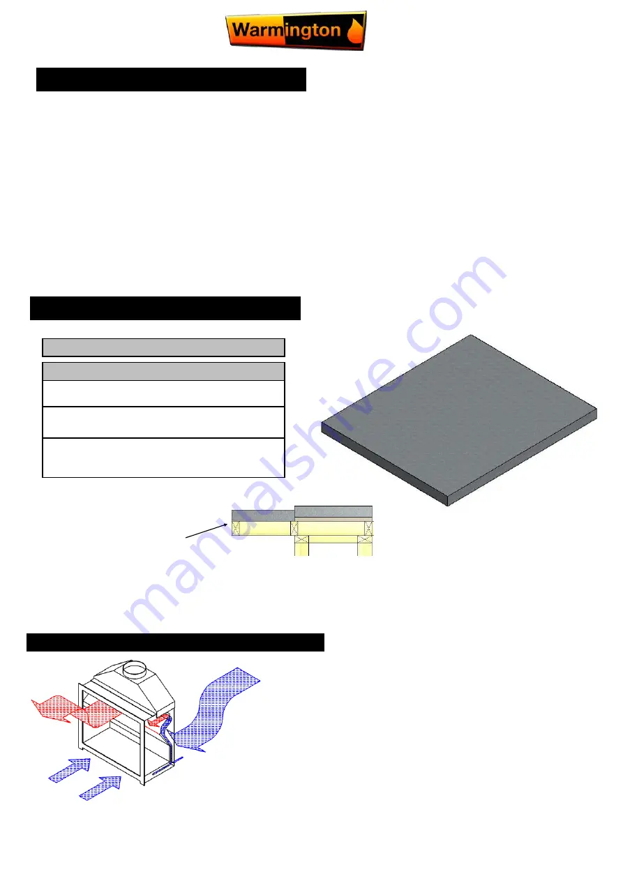
Hearth & Plinth
FIREBOX INSTALLATION
HEARTH & PLINTH CONSTRUCTION DETAILS
“
CAITEC
”
TECHONOLGY—ROOM AIR REPLACEMENT
Caitec
"
draws air from an external air source to ensure that the open fire has pre
-heated combustion air maximising efficiency while maintaining the home at con-
stant pressure equilibrium, reducing the risk of back drafting .
Ensure that the cavity is vented to Outside fresh Air and the Warmington will take
care of the rest. 2 x 100mm Diameter vent are required (Or equivalent to that.)
Builder to supply external air to the Cavity and the “Warmington Fire”
takes care of the rest.
NOTE : Point to consider regarding pressure differential.
Visit the Warmington website www.warmington for
“
Hebel
”
instruction (PDF download).
1.
All the dimensions are minimum.
2.
Fit the plinth into position. If installing on a wooden floor, ensure an insulating plinth is fitted as per the
specifications. Ensure the plinth is elevated to allow for finishing on the hearth. (See hearth and plinth
details).
3.
Fit the firebox & cabinet into position. Remove the cabinet top & bolt the firebox to the plinth or through to
the floor with the bolting points provided on the left and right hand sides of the firebox (seismic restraints).
4.
Ensure that Hi Temp Sealant is used between the Fire and Adaptor. Bolt into position with the Bolts in the
Left and Right Hand Sides of the Firebox.
5.
Install the Warmington Freestanding Flue System. (see page 8)
6.
Replace the top of the Freestanding cabinet.
This is a general Installation guide only. Contact a
“
NZHHA Installer
”
for installation advice.
Visit www.homeheat.co.nz, choose
“
members
” &
pick your area & fire type (wood / gas etc).
Note: Hearth and Plinth Construction.
For combustible flooring an insulating hearth and plinth of
75mm Hebel is required.
Plinth to be offset above hearth by the hearth finishing’s ( e.g.
tiles/granite/solid plaster/etc.
Raised hearth’s & plinth’s cantilevered must be adequately
supported to take the weight in accordance with the NZ
Building Code.
IMPORTANT NOTE:
*Note: If Solid Plastering the Heat Cell Structure, it is recommended to use a fibreglass mesh with a Latex Based Plaster to
minimise the chance of the Solid Plaster cracking. (See your Solid Plasterer for correct materials and applications).
This is a raised & cantilevered hearth.
See page 15 for further raised hearth
detail.


