background image

41

6. LEAK DETECTION METHODS

Do not apply any permanent inductive or capacitive loads to the circuit without making sure that it does 
not exceed the voltage and current ratings allowed for the equipment you are using. Intrinsically safe 
components  are  the  only  types  of  components  that  can  be  serviced  in  the  presence  of  a  flammable 
atmosphere. Replace components only with parts specified by the manufacturer. Other parts may cause 
refrigerant leakage.

Leak detection equipment should be set to the LFL percentage of the refrigerant and should be calibrated 
to the refrigerant used and the appropriate gas percentage (25% maximum) confirmed. Leak detection 
fluids are suitable for use with most refrigerants, but detergents containing chlorine should be avoided as 
chlorine can react with the refrigerant and corrode copper pipes. If a leak is suspected, all naked flames 
must be removed/extinguished. If a refrigerant leak is found that requires brazing, all refrigerant must be 
recovered from the system or isolated (by means of shut-off valves) in the part of the system away from 
the leak. Oxygen-free nitrogen (OFN) is then purged through the system - both before and during the 
brazing process.

4. WIRING

Under no circumstances should potential sources of ignition be used to search for or detect refrigerant 
leaks. A halide torch (or any other open flame detector) may not be used.

Check that the wiring is not exposed to wear, corrosion, excessive pressure, vibration, sharp edges or other 
adverse environmental influences. Inspection should also take into account wear or constant vibration 
from sources such as compressors or fans.

3. REPAIR OF INTRINSICALLY SAFE ELEMENTS

5. REFRIGERANT DETECTION

The  following  leak  detection  methods  are  considered  acceptable  for  systems  containing  flammable 
refrigerants. Electronic leak detectors should be used to detect flammable refrigerants, but sensitivity 
may not be sufficient or may require recalibration.

(Detection equipment should be calibrated in a refrigerant-free area.) Ensure that the detector is not a 
potential source of ignition and is suitable for the refrigerant being used.

Summary of Contents for OP-50

Page 1: ...OSUSZACZ POWIETRZA v 1 09 OP 50 50 D DEHUMIDIFIER PL EN...

Page 2: ...2...

Page 3: ...nak nie pogarszaj ce w a ciwo ci u ytkowych produktu Najnowsza wersja instrukcjiuwzgl dniaj caewentualnezmiany dost pnajestnawww warmtec pl Obs uga panelu steruj cego 9 Zasady u ytkowania 13 Monta urz...

Page 4: ...iami zawartymi w niniejszej instrukcji Instrukcja ta opisuje mo liwie jak najwi ksz liczb zdarze kt re u ytkownik napotyka podczas korzystania z urz dzenia Zawsze jednak nale y zachowa ostro no i rozw...

Page 5: ...ne u ywane i przechowywane w dobrze wentylowanym pomieszczeniu o powierzchni wi kszej ni 15 m a otwory obiegu powietrzaniemog by blokowaneprzez adneprzeszkody 5 Zabrania si podejmowania naprawy urz dz...

Page 6: ...Uchwyt transportowy Obudowa Wylot powietrza K ka transportowe Os ona filtra N ki 6 UWAGA Aby urz dzenie dzia a o poprawnie nale y pami ta o odpowiedniej temperaturze w kt rej powinno pracowa urz dzeni...

Page 7: ...lizgowych i przymocuj k ka po obu stronachosi Pozako czonejinstalacjiosi postawurz dzeniewpozycjipionowej 2 Metodamonta ustalowegouchwytu Jak przedstawiono na obrazku Zd 2 przykr dwie ruby w g rnej cz...

Page 8: ...iejscu otworu spustowego Nast pnieumie nakr tk spustow izamontujprzew dodp ywowy Gdy zbiornik jest pe ny urz dzenie automatycznie si wy cza i przechodzi w stan gotowo ci na wy wietlaczu pod wietlony z...

Page 9: ...MER Przycisk Instrukcja Obs ugi W czenie wy czenie urz dzenia Zmiana warto ci w zale no ci od aktualnie ustawianego statusu Zmiana poziomu wilgotno ci w zakresie od 10 do 95 RH 1 Zmiana warto ci timer...

Page 10: ...ejdzie w tryb ci g ego osuszania Wtymprzypadku abywy czy trybosuszania nale yu y przyciskuPOWER W celu zabezpieczenia urz dzenia przed uszkodzeniem je eli spr arka dzia a w trybie ci g ym przez 10 min...

Page 11: ...stawieniem czasu pracy do momentu jego wy czenia natomiast je eli urz dzenie jest wy czone zmiana ustawie timeraskutkujeustawieniemczasujakimamin doautomatycznegow czeniaurz dzenia 11 Automatyczne ods...

Page 12: ...mieszczeniu Ponownie naciskamy przycisk Timer na wy wietlaczu zacznie miga napis PRES Pressure Holding Jest to informacja o w czeniu lub wy czeniu ochronny ON OFF Za pomoc przycisk w i w czamy lub wy...

Page 13: ...og si mocno rozgrza podczas eksploatacji Nale y pilnowa aby dzieci nie zbli a y si do urz dzenia i nie bawi y si nim Nie pozw l aby urz dzenie zamok o Nie u ywaj urz dzenia w miejscach nara onym na za...

Page 14: ...i Urz dzenie pracuje w trybie odszraniania Pod cz wtyczk do gniazda zasilaj cego Sprawd przew d zasilaj cy oraz wy czniki w rozdzielni elektrycznej Po usuni ciu awarii w cz wy cznik lub wymie bezpiecz...

Page 15: ...i w urz dzeniu nale yregularnieopr nia zbiorniknawod 9 Poniewa efekt osuszania wi e si z temperatur i wilgotno ci otoczenia im wy sza temperatura i wilgotno otoczenia tryb osuszania jest efektywniejsz...

Page 16: ...ie ci nienie Klasa ochronno ci Temperatura pracy OP 50 230 V 50 Hz 50L dob przy 30 C RH80 30L dob przy 27 C RH60 750 W 27 C RH 60 900 W 30 C RH 80 3 4 A 27 C RH 60 4 0 A 30 C RH 80 1 0 MPa 2 5 MPa R29...

Page 17: ...elektrycznym i elektronicznym jest ograniczenie ilo ci odpad w powsta ych ze sprz tu zapewnienie odpowiedniego poziomu zbierania odzysku i recyklingu zu ytego sprz tu oraz zwi kszenie wiadomo ci spo...

Page 18: ...n by podzielony na cz ci Upewnij si e na obszarze prac naprawczych zosta y zapewnioneodpowiedniewarunkipoprzezkontrol materia w atwopalnych 1 3 Miejscepracy Je eli na urz dzeniu ch odniczym lub elemen...

Page 19: ...i absolutnie konieczne jest doprowadzenie zasilania do urz dzenia podczas serwisowania w wczas w najbardziej krytycznym punkcie powinna znajdowa si trwale dzia aj ca forma wykrywania wyciek w abyostrz...

Page 20: ...y wyciek w ale czu o mo e by niewystarczaj ca lub mo e wymaga ponownejkalibracji Sprawd czy okablowanie nie jest nara one na zu ycie korozj nadmierny nacisk wibracje ostre kraw dzie ani inne niekorzys...

Page 21: ...a dop ki w uk adzie nie b dzie czynnika ch odniczego W przypadku zastosowania ko cowego adunku OFN uk ad powinien zosta odpowietrzony do ci nienia atmosferycznego aby umo liwi przeprowadzenie prac Ta...

Page 22: ...tki azw aszczaniewbutlach j Po prawid owym nape nieniu butli i zako czeniu procesu upewnij si e zostan niezw ocznie usuni te azaworyzostan zamkni te Je li spr arki lub oleje spr arkowe maj zosta usuni...

Page 23: ...n Instructions for Control Panel Tips Troubleshooting Environmental Protection and Recycling Rules for the repair of equipment containing R290 refrigerant Function Description Safety Rules Technical S...

Page 24: ...24...

Page 25: ...azard Beawarethatrefrigerantsmaynothaveanodor 1 This appliance can be used by children aged 8 years and older and persons with reduced physical sensory or mental capabilities or lack of experience and...

Page 26: ...fied technicianswhoareauthorizedtoworkwithflammablerefrigerants GWP GlobalWarmingPotential oftherefrigerant 3 26 It is forbidden to undertake repairs of the device by persons who do not have the appro...

Page 27: ...Inlet Handle Case Air Outlet Wheels Filter Cover Support 27 ATTENTION For the device to work properly remember about the appropriate temperature in which the device should work 5 C 35 C Operation bel...

Page 28: ...s of the axle After the axis installation is completed placethedeviceinanuprightposition 1 Installationmethod As shown in Fig 2 fix the two screws on the top of the body rotate the steel pipe 180 degr...

Page 29: ...fiercancontinuetowork In a situation where the water tank will require frequent emptying you should decide for a uninterrupteddrainagesystem AsshowninFig 3Torestoretheoperationofthedehumidifier firstr...

Page 30: ...panel POWER TIMER Button User manual Turning ON OFF the device Changing the value depending on the currently set status 1 Changing the humidity level ranging from 10 to 95 RH 2 Changing the timer valu...

Page 31: ...thePOWERbuttontoturnoffthedehumidificationmode Fullwatertank Memory of the last settings in the event of a sudden power failure or accidental disconnection of the power plug when the power is restored...

Page 32: ...heworkingtimeuntilit is turned off while if the device is turned off changing the timer settings results in setting the timethatmustpassuntilthedeviceisautomaticallyturnedon 32 Automatic defrosting Tu...

Page 33: ...ngadvancedparameters 1 Humidity correction setting to set the desired room humidity value press and hold the Timer button for more than 10 seconds The display will show the current relative humidity R...

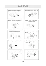
Page 34: ...during use Keep children away from the appliance anddonotplaywithit Do not let the device get wet Do not use the device in places prone to flooding Whenplanningtoplacethedeviceinaroom placethedeviceon...

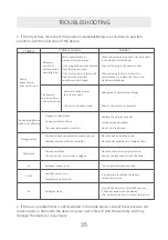
Page 35: ...t the plug to the power socket Check the power cord and the circuit breakers in the electrical switchboard After removing the fault turn on the circuit breaker or replace the fuse in the electrical sw...

Page 36: ...the display and the actual humidity is a normalphenomenon theindicationsareaffectedbylocation environmentalconditions andtemperatureinthedehumidifiedroom 5 To avoid flooding and excessive moisture bu...

Page 37: ...ss Working temperature OP 50 230 V 50 Hz 50L day by 30 C RH80 30L day by 27 C RH60 750 W 27 C RH 60 900 W 30 C RH 80 3 4 A 27 C RH 60 4 0 A 30 C RH 80 1 0 MPa 2 5 MPa R290 200 g I 5 C 35 C Refrigerant...

Page 38: ...ipment The user of equipment intended for households is obliged to return waste electrical and electronic equipment to a collector a er its use However it should be remembered that products belonging...

Page 39: ...ace Before star ng work visually inspect the area around the equipment to make sure that there are no other ammablesubstancesandnoriskofigni on Nosmokingsignsshouldbepostedinaprominentplace 1 7 Adequa...

Page 40: ...eandlegible ifmarkingsandsignsareillegible theyshouldbecorrected the refrigerant pipe or refrigeration components are installed in a location that is not exposed to any substance that may corrode the...

Page 41: ...requires brazing all refrigerant must be recovered from the system or isolated by means of shut off valves in the part of the system away from the leak Oxygen free nitrogen OFN is then purged through...

Page 42: ...uld be taken in case analysis is required before reusing the recovered refrigerant Itisessen althatelectricalpowerisavailablebeforestar ngthejob Tagthesystema erloadingiscomplete ifnotalready agged re...

Page 43: ...and marked with reclaimed refrigerant i e special refrigerant recovery cylinders Cylinders should be complete with pressure relief valve and associated shut o valvesingoodworkingorder Emptyrecoverycyl...

Page 44: ...44 NOTATKI...

Page 45: ...45...

Page 46: ...46...

Page 47: ...47...

Page 48: ...www warmtec pl v 1 09...

Reviews: