background image

©2016 Warn Industries, Inc. WARN® and the WARN logo are trademarks of Warn Industries Inc.

 4 

101320A0

I N S T A L L A T I O N   I N S T R U C T I O N S

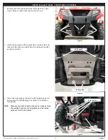
1.  Remove the front plastic guard by removing the six side 

screws (three on each side) and two front screws.

2.  Install winch mount with two bolts (B3), washers (B1) and 

lock nuts (B2) and two u-bolts (B6), four lock washers (B4) 

and four nuts (B5). 


3.  Slide winch into place and secure with hardware found in 

your winch kit and following your winch kit installation 

instructions.

NOTE:    There are two sets of bolt holes you can choose from.  

The outside holes are for long drum and the inside 

holes are for the short drum.

Figure 1

Figure 2

Figure 3

B6, B4 and B5

B3, B1 and B2

B3, B1 and B2

Winch

Summary of Contents for 101316

Page 1: ...delectricalterminals Alwaysinstallterminalbootsasdirectedininstallationinstructions Alwaysuseappropriateandadequatecareinliftingcomponentsintoplace Alwaysinsurecomponentswillremainsecureduringinstallationandoperation Alwaystightenallnutsandboltssecurely pertheinstallationinstructions Alwaysperformregularinspectionsandmaintenanceontheplowmechanism fasteners cableandrelatedhardware Alwaysreplaceallw...

Page 2: ...nce Care page 5 T O O L S R E Q U I R E D Metric wrenches Metric sockets Fine tooth reciprocating saw Small disk sander T O R Q U E S P E C I F I C A T I O N S Please use the recommended torque specifications when assembling this product unless otherwise specified in the instructions FASTENERSIZE FASTENERTORQUE FASTENERSIZE FASTENERTORQUE lb ft N m lb ft N m 1 4 8 11 M4 2 3 5 16 17 23 M5 4 5 6 3 8...

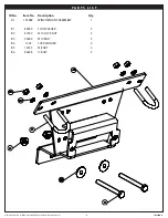
Page 3: ...e trademarks ofWarn Industries Inc 3 101320A0 P A R T S L I S T ID No Item No Description Qty A1 101582 WINCH MOUNT ASSEMBLY 1 B1 89389 FLAT WASHER 2 B2 87232 M10 LOCK NUT 2 B3 90609 M10 BOLT 2 B4 1402 LOCK WASHER 4 B5 13455 M8 NUT 4 B6 86678 U BOLT 2 ...

Page 4: ...ll winch mount with two bolts B3 washers B1 and lock nuts B2 and two u bolts B6 four lock washers B4 and four nuts B5 3 Slide winch into place and secure with hardware found in your winch kit and following your winch kit installation instructions NOTE There are two sets of bolt holes you can choose from The outside holes are for long drum and the inside holes are for the short drum Figure 1 Figure...

Page 5: ...stic in place and secure with hardware removed in step 1 10 Installation is now complete I N S T A L L A T I O N I N S T R U C T I O N S Figure 5 Figure 6 Figure 7 M A I N T E N A N C E C A R E 1 Inspect all parts on the winch winch mount and related hardware prior to each use Replace all hardware that appears rusted or deformed 2 Inspect all nuts and bolts on the winch winch mount and related har...

Reviews: