background image

©2018 Warn Industries, Inc. WARN® and the WARN logo are trademarks of Warn Industries Inc.

 2 

101799A0


C A U T I O N

MOVING PARTS ENTANGLEMENT HAZARD

Failure to observe these instructions could lead to minor or moderate injury

• 

Always

 take time to fully read and understand the installation and Operations Guide included with this product.

• 

Never

 operate this product if you are under 16 years of age.

• 

Never

 operate this product when under the influence of drugs, alcohol or medications.

Read installation and operating instructions thoroughly.

T A B L E   O F   C O N T E N T S

Tools Required .............................................................................................................................page 2

Torque Specifications ................................................................................................................page 3

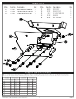
Parts List.........................................................................................................................................page 3

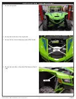
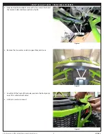
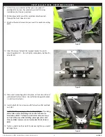
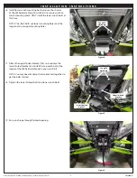
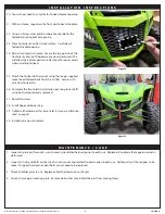
Installation ................................................................................................................................page 4-8

Maintenance/Care ......................................................................................................................page 8

T O O L S   R E Q U I R E D

-  Metric wrenches

-  Metric sockets

-  Fine tooth reciprocating saw

N O T I C E

EQUIPMENT DAMAGE

• 

Never

 tow vehicle by attaching a tow bar to the eyelets on the bumper.  

• 

Never

 attach tow bars directly to the bumper.  Damage to bumper may occur.  WARN bumpers are not designed to be used for flat towing.  Consult with the manufacturer of your tow bar system for the proper vehicle tow 

bar brackets..

Read installation and operating instructions thoroughly.

Summary of Contents for 101672

Page 1: ...delectricalterminals Alwaysinstallterminalbootsasdirectedininstallationinstructions Alwaysuseappropriateandadequatecareinliftingcomponentsintoplace Alwaysinsurecomponentswillremainsecureduringinstallationandoperation Alwaystightenallnutsandboltssecurely pertheinstallationinstructions Alwaysperformregularinspectionsandmaintenanceontheplowmechanism fasteners cableandrelatedhardware Alwaysreplaceallw...

Page 2: ...edications Read installation and operating instructions thoroughly T A B L E O F C O N T E N T S Tools Required page 2 Torque Specifications page 3 Parts List page 3 Installation page 4 8 Maintenance Care page 8 T O O L S R E Q U I R E D Metric wrenches Metric sockets Fine tooth reciprocating saw N O T I C E EQUIPMENT DAMAGE Nevertowvehiclebyattachingatowbartotheeyeletsonthebumper Neverattachtowba...

Page 3: ... N S Please use the recommended torque specifications when assembling this product unless otherwise specified in the instructions FASTENERSIZE FASTENERTORQUE FASTENERSIZE FASTENERTORQUE lb ft N m lb ft N m 1 4 8 11 M4 2 3 5 16 17 23 M5 4 5 6 3 8 30 40 M6 7 5 10 7 16 48 66 M8 18 25 1 2 74 100 M10 37 50 9 16 106 144 5 8 148 200 3 4 269 364 ID No Item No Description Qty B1 86814 M8 U BOLT 2 B2 22491 ...

Page 4: ...ies Inc 4 101799A0 I N S T A L L A T I O N I N S T R U C T I O N S 1 Remove vehicle hood 2 Remove the two front pins from top of grille 3 Remove the four screws holding top portion of the fenders 4 Remove the screw from in the inside of the fender well both sides Remove Remove ...

Page 5: ...two screws that hold the lower air dam and lower portion of grille 6 Remove the two center air dam support bracket screws 7 Carefully lift the front of the fender and slide the front plastic away from vehicle both sides 8 Grille can now be removed I N S T A L L A T I O N I N S T R U C T I O N S Figure 4 Figure 5 Figure 6 Remove Remove ...

Page 6: ...irlead A2 support bracket to winch mounting plate A1 Do not tighten completely to allow for adjustment 13 Slide winch mounting plate into place in front of winch and just behind the front tubes Lower fairlead support bracket is not shown in photo 14 Install u bolts B1 and secure with flat washers B3 and lock nuts B2 Helpful Hint for passenger side u bolt installation If working alone take a piece ...

Page 7: ...ting plate ONLY install the lower winch bolts at this time NOTE The short bolts use lower mounting holes and the longer bolts use upper mounting holes 17 Attach the upper fairlead bracket A3 so it overlaps the lower fairlead bracket and install the top winch bolts the longer of the M8 hardware found in your winch kit NOTE You may need to clamp the two brackets together to get the bolts started 18 ...

Page 8: ...e mount using the longer supplied socket head fairlead bolts from this kit B5 Secure with nuts from fairlead kit 26 Complete the front plastic installation securing lower half using hardware previously removed 27 Reinstall air dam 28 Install hook and hook strap 29 Tighten all hardware at this time refer to torque specification chart on page 3 30 Installation is now complete M A I N T E N A N C E C...

Reviews: