


©2016 Warn Industries, Inc. WARN® and the WARN logo are trademarks of Warn Industries Inc.
4
103058A0
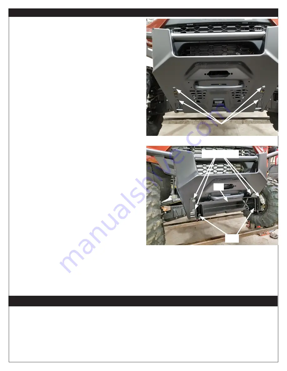
Figure 2
I N S T A L L A T I O N I N S T R U C T I O N S
1. You will be installing the front plow mount to the stock
bumper mounting holes seen in Figure 1.
2. Attach plow mount (A1) with support plates
(not shown)
(A3) to
the front of the bumper using two M12 flange bolts (B1) and
M12 flange nuts (B2). Refer to exploded view on page 3.
3. Attach plow flange using the retaining pin (B3) on each side
(not shown in image - refer to exploded view on page 3
).
Your plow mount installation is complete.
4. Tighten all hardware now. Refer to torque specifications on
page 2.
5. Secure fairlead to fairlead bracket with hardware from your
winch kit.
6. Install winch per winch installation instructions.
7. Install your plow to plow flange, per your specific plow
instructions.
8. Tighten all hardware now. Refer to torque specifications on
page 2.
Figure 1
M A I N T E N A N C E / C A R E
1. Inspect all parts on the winch, winch mount, and related hardware prior to each use. Replace all hardware that appears rusted or
deformed.
2. Inspect all nuts and bolts on the winch, winch mount and related hardware prior to each use. Tighten all nuts that appear to be
loose. Stripped, fractured, or bent bolts or nuts need to be replaced.
3. Check all cables prior to use. Replace cables that look worn or frayed.
4. Check all moving or rotating parts. Remove debris that may inhibit the part from moving freely.
A3, B1 & B2
A1
B3


