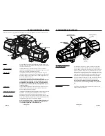
Mount Winch:
1. Choose a mounting location that is sufficiently
strong enough to withstand the maximum
pulling capacity of your winch.
2. Install your mounting bracket per your specific
mounting kit instructions.
3. Fasten fairlead to mounting bracket using
the (2) bolts specified above for your specific
mounting orientation. See the
Mounting
Orientation
section for hardware specifics
.
4. Set the (4) flanged nuts into pockets of winch
feet.
5. Thread the hook loop end of the rope through
the opening of mounting bracket and fairlead.
NOTE: Do not remove plastic wrap from
remaining rope on drum at this time.
6. Set winch in mount.
7. See table below to confirm required bolt length.
Plate Thickness
Bolt Length
7 mm (1/4”)
32 mm
10 mm (3/8”)
40 mm
13 mm (1/2”)
40 mm
8. Review mounting orientation on page 10 for
bolt sizing.
9. Install bolts and tighten to 41 to 47 Nm (30-35
ft. lbs.).
WARNING
Always con rm required bolt length to
ensure proper thread engagement.
10. Attach hook to winch rope loop.
11. Attach hook strap to hook.
12. Remove plastic wrap from remaining rope on
drum.
13. Mounting your winch is now complete. Check
all hardware to be sure it is tight and to torque.
You can now move on to Install the Wiring.
NOTE
OPTIONAL SYNTHETIC ROPE INSTALLATION
For synthetic rope models, be sure to fully read these
instructions to familiarize yourself completely with
the Advanced Wireless Remote Control operation
before you attempt to install the optional synthetic
rope. See your WARN® Synthetic Rope Installation
Instruction Manual for detailed synthetic rope
installation instructions.
WARN INDUSTRIES
13
MOUNTING
Step 2 - Install the Wiring
WARNING
To prevent serious injury or death. Always
place the supplied terminal boots on wires and terminals as
directed by the installation instructions.
WARNING
To prevent serious injury or death from
electrical re:
Never route electrical cables across sharp edges.
Never route electrical cables near parts that get
hot.
Never route electrical cables through or near
moving parts.
Avoid pinch and wear/abrasion points when
installing all electrical cables.
WARNING
Always insulate and protect all exposed wiring
and electrical terminals.
NOTICE A fully charged battery and good connections are
essential to the proper operation of your winch. The minimum
requirement for a 12 volt DC battery is 650 Cold Cranking Amps.
Route battery connection cables in areas which
will not cause them to chafe or cut through the
insulation causing a potential short circuit.
The winch power wire must be routed to the
battery. A direct battery connection of the power
(red) and ground (black) cable is required.
Do not
connect ground to vehicle chassis.
Routing the battery connection cables may
require removal of vehicle facia or body parts.
Always route battery cables along a path that
allows the cables to be secured with zip ties.
WARNING
Loose or unsecured power cables can cause
serious injury or death.
Always protect power cables from sharp edges,
areas that get too hot to touch with your hand and
any moving parts.
1. Plan the routing path.
2. Loosely secure power cables along path.
3. Confirm power cables are protected from sharp
edges, heat and moving parts. Consider chassis
flex and vibration which might damage cable.
4. Carefully inspect electrical cable routing. Zip tie
and secure electrical cables. Zip ties should be
snug, but not cutting into wire insulation. Use
electrical tape, pieces of rubber hose or electrical
conduit to protect electrical cables and wire
harness where needed to avoid electrical cable
insulation wear or abrasion.
5. FIRST, attach the winch power (red) cable to the
positive (+) battery terminal. SECOND, attach the
ground (black) cable to the negative (-) battery
terminal.
WARNING
Always connect red (+) power cable ONLY to the
positive (+) terminal of the battery.
WARNING
Always connect black ground (-) power cable ONLY
to the negative (-) terminal of the battery.
Step 3 - System Check
Perform system check:
1. Check fasteners and make sure they are tight and
to proper torque
2. Verify the wireless control activation switch light
turns ON. A flashing green light appears in the
switch. If light does not turn on, immediately
check to ensure power cables are correctly
connected to the battery, red to (+) and black to (-).
If not, disconnect and reconnect as instructed.
3. Verify all electrical wiring to all components is
correct and be certain that all connections are
tight.
4. Verify there is no exposed/bare wiring, terminals or
cable insulation damage.
5. Read The Basic Guide to Winching Techniques
completely before operating your winch.
6. Charge remote.
Once you have performed a system check, you are
ready to perform “First Time Operating Instructions”.
Ground (black) Cable
Power (red) Cable
Wireless Control
Activation Switch
Control Pack Ground
Wire
WARN INDUSTRIES
14
ELECTRICAL CONNECTIONS
92821A4
92821A4


