COMBO-401 i/501 i
OPERATOR’S MANUAL
9
2.
Connections
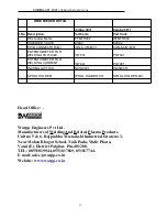
(The user should choose the power cables, switches, fuses and power switches as specified in table )
2.1 Connections of the power supply cable and the grounding cable
Methods and requirements
Make sure that power supply panel is off before connecting.
Do not connect with wet hands.
Do not place anything on the power supply cable.
Make sure all the connections are proper.
Connect the green-yellow wire of the three-phase input cable to the grounding wire on the switchboard
properly.
2.2 The output cable connection of manual welding
Methods and requirements:
Please make sure the power switch is off before connecting.
Connect the copper connector of workpiece cable to the ‘+’ and ‘--’ output socket that on the welding power
source. When it is negative connection
,
the welding electrode holder should be connected to the ‘+’. When it is
positive connection
,
the welding electrode holder should be connected to the ‘--’
The welding cable and workpiece should be properly connected by bolts, and have good contact.
2.3 Connections of Gas-shielded Welding
2.3.1 Connection of the output cable
Methods and requirements
Please make sure the power switch is cut off before connecting.
Connect the copper connector of wire feeder cable to ‘+’ output that on the welding power source;
Connect the copper connector of workpiece cable to ‘--’ output that on the welding power source, connect the
other side to workpiece with bolts;
Insert the aviation plug(six cores) of control cable into the control socket(six cores) of wire feeder, then tighten
the ring nut, connect the other side of control cable to wire feeder.
2.3.2 Connections of the power source, wire feeder and welding torch(please refer to figure 1)
Methods and requirements
Make sure the power switch is cut off before connecting;
Wire feeders that produced by our company are requested to match with the certain welding machine.
Otherwise the welding performance maybe bad and even damage the machine;
Insert the aviation plug(six cores) of control cable into the control socket(six cores) of wire feeder, then
tighten the ring nut;
Aim the control plug of the welding gun at the guide slot, then insert it into the control output socket (2 pins),
then tighten the ring nut. After the connector of welding torch aiming at guide slot, you can insert it completely.
And then turn 90° by clockwise rotation and tighten the bolts; Connect the gas pipe of welding torch to the gas
output connector of wire feeder, and then tighten the nuts.
2.3.3 Connections of the gas cylinder and gas adjuster
Methods and requirements
Install the gas regulator to the gas cylinder.
Connect the gas heater to the heater’s power source socket on the back panel of the machine.
Connect the gas hose of the wire feeder to the gas output connector of the gas heater.
3. Directions of the manual welding mode
Specification
COMBO-401 i
COMBO-501 i
Switch capacity
(
A
)
40
63
Fuse capacity
(
A
)
32
40
Section surface of power supply cables
(
mm
2
)
4
6
Section surface of grounding cables
(
mm
2
)
4
6


