pb025nmdl4sm-rev1119
sandpiperpump
.
com
Model PB¼ Non-Metallic •
17
Diaphragm and Rod Servicing
3
3.1
3.2
22
19
9
19
18
9
8
8
8.1
8.2
12
18
12
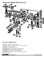
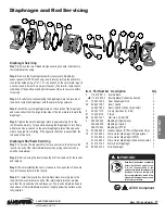
Diaphragm Servicing
Step 1:
Remove the two V-Band clamps securing the outer chambers to
the intermediate housing.
Step 2:
Remove the diaphragm assembly (outer plate, diaphragm,
spacer gasket (for PFTE units only, inner plate) by turning the assembly
counterclockwise using a 1/2" (1.27 cm) wrench on the outer plate lugs. (If
a socket is used, it must be a six-point socket.) The interior components
consisting of the shaft seal and pilot valve assembly are now accessible
for service.
Step 3:
Procedures for reassembling the diaphragms are the reverse of
the above. Install the diaphragm with the natural bulge outward.
Step 4:
Install the outer diaphragm plate on the outside of the diaphragm
and make certain that the large radius side of the inner plate is toward the
diaphragm.
Step 5:
Tighten the outer diaphragm plate to approximately 30 in./lbs.
(3.39 Newton meters). Torque while allowing the diaphragm to turn freely
with plates. Use a wrench on the outer diaphragm plate of the opposite
side to keep rod from rotating. If the opposite chamber is assembled, the
rod need not be held.
Diaphragm Rod Seals Servicing
Step 1:
To service the rod seals first remove pilot valve, then remove the
inserts on each of the intermediate brackets by prying them out with a
small flat screwdriver.
Step 2:
After removing the inserts take the K-R rod seals out of the inserts
and replace.
Step 3:
When reinstalling the seals, make sure the open side of the seals
face into thecounterbore in the inserts.
Step 4:
To install the inserts into intermediate bracket, simply press the
insert into the counterbore in each of the intermediate bracket, making
sure that the closed side of insert faces out. The inserts should be flush to
the surface of the intermediate bracket or slightly below the surface when
fully installed.
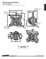
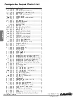
Item Part Number Description
Qty
3 114.019.551 F Intermediate
1
114.019.503 F Intermediate (Conductive Acetal)
1
3.1 720.031.359 Seal, Diaphragm Rod
2
3.2 449.021.551 Insert, Gland
2
449.021.503 Insert, Gland (Conductive Acetal)
2
8 200.057.115 Clamp (Includes 81 & 82)
2
8.1 100.002.115 T-Bolt
2
8.2 545.027.337 Nut, Hex, 1/4-28UNF
2
9 286.069.354 Diaphragm (Santoprene)
4
286.069.356 Diaphragm (Hytrel)
4
286.070.600 Diaphragm (PTFE)
4
12 360.086.360 Gasket, Spacer (PTFE Configuration Only) 2
18 612.146.552 Plate, Outer Diaphragm (Polypropylene)
2
612.146.520 Plate, Outer Diaphragm (PVDF)
2
612.146.502 Plate, Outer Diaphragm (Conductive Acetal) 2
19 612.147.150 Plate, Inner Diaphragm
2
22 685.046.120 Rod, Diaphragm
1
ATEX Compliant
IMPORTANT
Read these instructions completely,
before installation and start-up.
It is the responsibility of the
purchaser to retain this manual for
reference. Failure to comply with
the recommendations stated in this
manual will damage the pump, and
void factory warranty.
5: WET END

