background image

s05conductiveactelsm-rev1218

sandpiperpump

.

com

Model S05 Conductive Acetal 

15

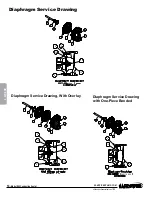
Diaphragm Service Drawing 

with One-Piece Bonded

DIAPHRAGM  SERVICING

To service the diaphragms first shut off the 

suction, then shut off the discharge lines to the 

pump. Shut off the compressed air supply, bleed 

the pressure from the pump, and disconnect 

the air supply line from the pump. Drain any 

remaining liquid from the pump.

Step #1: See the pump composite repair 

parts drawing, and the diaphragm servicing 

illustration.

Using a 1/2" wrench or socket, remove the 

16 capscrews (items 9 & 10), and flanged nuts 

that fasten the elbows (items 16 and 17) to the 

outer chambers (items 13). Remove the elbows 

with the manifolds and spacers attached.

Step #2: Removing the outer chambers.

Using a 1/2" wrench or socket, remove the 

16 capscrews (items 9 and 10), and flanged nuts 

that fasten the outer chambers, diaphragms, and 

intermediate (item 4) together.

Step #3: Removing the diaphragm 

assemblies.

Use a 3/4" (19mm) wrench or six pointed 

socket to remove the diaphragm assemblies 

(outer plate, diaphragm, and inner plate) 

from the diaphragm rod (item 30) by turning 

counterclockwise.

Insert a 6-32 set screw into the smaller 

tapped hole in the inner diaphragm plate (item 

27). Insert the protruding stud and the 6-32 

fastener loosely into a vise. Use a 3/4" wrench 

or socket to remove the outer diaphragm plate 

(item 26) by turning counterclockwise. Inspect 

the diaphragm (item 14) for cuts, punctures, 

abrasive wear or chemical attack. Replace the 

diaphragms if necessary.

Step #4: Installing the diaphragms.

Push the threaded stud of the outer 

diaphragm plate through the center hole of the 

diaphragm. Thread the inner plate clockwise 

onto the stud. Insert the loose assembly with 

the above 6-32 fastener back into the vise. 

Use a torque wrench to tighten the diaphragm 

assembly together to 90 in lbs. (10.17 Newton 

meters) 120 in lbs. Santoprene (13.56 Newton 

meters). Allow a minimum of 15 minutes 

to elapse after torquing, then re-torque the 

assembly to compensate for stress relaxation 

in the clamped assembly.

Step #5: Installing the diaphragm assemblies 

to the pump.

Make sure the bumper (item 6) is installed 

over the diaphragm rod.

Thread the stud of the one diaphragm 

assembly clockwise into the tapped hole at the 

end of the diaphragm rod (item 30) until the inner 

diaphragm plate is flush to the end of the rod. 

Insert rod into pump.

Align the bolt holes in the diaphragm with the 

bolt pattern in the intermediate (item 4).

Fasten the outer chamber (item 13) to the 

pump, using the capscrews (items 9 and 10) 

and flanged nuts. 

On the opposite side of the pump, pull the 

diaphragm rod out as far as possible. Make 

sure the bumper (item 6) is installed over the 

diaphragm rod. 

Thread the stud of the remaining diaphragm 

assembly clockwise into the tapped hole at the 

end of the diaphragm rod (item 30) as far as 

possible and still allow for alignment of the bolt 

holes in the diaphragm with the bolt pattern 

in the inner chamber. Install diaphragms with 

convolutions facing towards center of pump. 

See sectional view on previous page.

Fasten the remaining outer chamber (item 

13) to the pump, using the capscrews (items 9 

and 10) and flanged nuts.

Step #6: Re-install the elbow/spacer/

manifold assemblies to the pump, using the 

capscrews (items 9 & 10) and flanged  nuts.

The pump is now ready to be  

re-installed, connected and returned to operation.
OVERLAY DIAPHRAGM SERVICING 

The overlay diaphragm (item 15) 

is designed to fit snugly over the exterior 

of the standard TPE diaphragm (item14). 


ONE PIECE DIAPHRAGM SERVICING (Bonded 

PTFE with intergral plate)

The One Piece diaphragm has a treaded 

stud installed in the intergral plate at the factory. 

The inner diaphragm plate has a through hole 

instead of a threaded hole.

Place the inner plate over the diaphragm 

stud and thread the first diaphragm / inner plate 

onto the diapragm rod only until the inner plate 

contacts the rod. Do not tighten. 

A small amount of grease may be applied 

between the inner plate and the diaphragm to 

facilitate assembly.

Insert the diaphragm / rod assembly into the 

pump and install the outer chamber. Turn the 

pump over and thread the second daiphragm 

Diaphragm  Servicing

IMPORTANT

Read these instructions completely, 

before installation and start-up. 

It is the responsibility of the 

purchaser to retain this manual for 

reference. Failure to comply with 

the recommendations stated in this 

manual will damage the pump, and 

void factory warranty.

/ inner plate onto the diaphragm rod. Turn the 

diapragm until the inner plate contacts the 

rod and hand tighten the assembly. Continue 

tightening until the bolt holes align with the 

inner chamber holes. DO NOT LEAVE THE 

ASSEMBLY LOOSE. 

5: WET END

Summary of Contents for Sandpiper S05

Page 1: ... Inc A Unit of IDEX Corporation 800 N Main St Mansfield Ohio 44902 USA Telephone 419 524 8388 Fax 419 522 7867 SANDPIPERPUMP COM Copyright 2016 Warren Rupp Inc All rights reserved 1 PUMP SPECS 2 INSTAL OP 3 EXP VIEW 4 AIR END 5 WET END 6 OPTIONAL 7 WARRANTY SERVICE OPERATING MANUAL Original Instructions ...

Page 2: ...to be powered by compressed natural gas Powering the pump with natural gas will void the warranty Use safe practices when lifting kg 1 Ambient temperature range is as specified in tables 1 to 3 on the next page per Annex I of DEKRA 18ATEX0094X 2 ATEX compliant pumps are suitable for use in explosive atmospheres when the equipment is properly grounded in accordance with local electrical codes 3 Non...

Page 3: ...T5 T100 X 20 C to 50 C 20 C to 100 C T5 T100 X Ambient Temperature Range C Process Temperature Range C 20 C to 60 C 20 C to 150 C 1 Per CSA standards ANSI LC6 2018 US Canadian Technical Letter R14 G Series Natural Gas Models are restricted to 20 C to 80 C process temperature Note The ambient temperature range and the process temperature range should not exceed the operating temperature range of th...

Page 4: ...DED VIEW 7 Composite Drawings Parts List Materials Code SECTION 4 AIR END 10 Air Distribution Valve Assembly Air Valve with Stroke Indicator Option Pilot Valve Intermediate Assembly SECTION 5 WET END 14 Diaphragm Drawing Diaphragm Servicing SECTION 6 OPTIONAL CONFIGURATIONS 16 Solenoid Shifted Air Valve Dual Port SECTION 7 WARRANTY CERTIFICATES 18 Warranty CE Declaration of Conformity Machinery AT...

Page 5: ...phragm Check Valve Non Wetted Porting Pump Pump Kit Brand Size Valve Level Material Check Valves Seat Material Options Style Options Options S XX X X X X X X X X X XX Model S __ ____ __ __ __ __ __ __ __ __ __ ____ fill in from pump nameplate Your Model ATEX Detail IEC EEX m T4 Note Pump models equipped with these explosion proof solenoid kit options E1 E3 E5 E7 E8 or E9 are certified and approved...

Page 6: ...s outstanding abrasion and impact resistance along with environmental stress cracking resistance 180 F 82 C 35 F 37 C Urethane Shows good resistance to abrasives Has poor resistance to most solvents and oils 150 F 66 C 32 F 0 C Virgin PTFE PFA TFE Chemically inert virtually impervious Very few chemicals are known to chemically react with PTFE molten alkali metals turbulent liquid or gaseous fluori...

Page 7: ...h Suction And Discharge Ports Are available In BSP tapered Internal BSP tapered external Suction Port NPT Internal 1 NPT External Integral Muffler 3 8 NPT Exhaust Port For Metal Muffler or Piping Exhaust Air In Submerged Applications Discharge Port 1 2 NPT Internal 1 NPT External Manifold Can Rotate 90 From Vertical Centerline Air Inlet 1 4 NPT DIMENSION A B Integral Muffler 4 1 16 7 1 16 Metal Mu...

Page 8: ... NPT Internal 1 NPT External Integral Muffler 3 8 NPT Exhaust Port For Metal Muffler or Piping Exhaust Air In Submerged Applications Discharge Port 1 2 NPT Internal 1 NPT External 44mm Manifold Can Rotate 90 From Vertical Centerline Air Inlet 1 4 NPT DIMENSION A B Integral Muffler 103mm 179mm Metal Muffler 130mm 206mm S05 Conductive Acetal Dimensions in inches metric dimensions in brackets Dimensi...

Page 9: ...suction side check valve and into the outer fluid chamber Suction side stroking also initiates the reciprocating shifting stroking or cycling action of the pump The suction diaphragm s movement is mechanically pulled through its stroke The diaphragm s inner plate makes contact with an actuator plunger aligned to shift the pilot signaling valve Once actuated the pilot valve sends a pressure signal ...

Page 10: ...xhaust air causing the pump to cycle erratically or stop operating Water in the air supply can be reduced by using a point of use air dryer Air Inlet And Priming To start the pump slightly open the air shut off valve After the pump primes the air valve can be opened to increase air flow as desired If opening the valve increases cycling rate but does not increase the rate of flow cavitation has occ...

Page 11: ... meets or exceeds air supply pressure Increase the inlet air pressure to the pump Pump is designed for 1 1 pressure ratio at zero flow Does not apply to high pressure 2 1 units Cavitation on suction side Check suction move pump closer to product Lack of air line size PSI CFM Check the air line size length compressor capacity Excessive suction lift For lifts exceeding 20 of liquid filling the chamb...

Page 12: ... 18 3 476 221 000 AIR END KIT Seals O ring Gaskets Retaining Rings Air Valve Assembly Pilot Valve Assembly 476 202 360 WET END KIT Nitrile Diaphragms Nitrile Check Balls PTFE Seats and PTFE Seals 476 202 354 WET END KIT Santoprene Diaphragms Santoprene Check Balls PTFE Seats and PTFE Seals 476 202 357 WET END KIT Polyurethane Diaphragms Nitrile Spacer Gaskets Santoprene Check Balls PTFE Seats and ...

Page 13: ...r Outer 2 14 286 095 354 Diaphragm 2 286 095 357 Diaphragm 2 286 095 360 Diaphragm 2 286 116 000 Diaphragm One Piece Bonded 2 15 286 096 600 Diaphragm Overlay 2 16 312 106 502 Elbow Suction 2 17 312 112 502 Elbow Discharge 2 18 360 100 379 Gasket Air Inlet 1 19 360 108 360 Gasket Pilot Valve 1 20 360 102 360 Gasket Air Valve 1 21 518 138 502 Manifold NPT 2 518 138 502E Manifold BSPT Tapered 2 22 5...

Page 14: ... Color coded GREEN 366 Food Grade Nitrile 368 Food Grade EPDM 371 Philthane Tuftane 374 Carboxylated Nitrile 375 Fluorinated Nitrile 378 High Density Polypropylene 379 Conductive Nitrile 408 Cork and Neoprene 425 Compressed Fibre 426 Blue Gard 440 Vegetable Fibre 500 Delrin 500 502 Conductive Acetal ESD 800 503 Conductive Acetal Glass Filled 506 Delrin 150 520 Injection Molded PVDF Natural color 5...

Page 15: ...ratches or other contaminants Remove the sleeve if needed and replace with a new sleeve and spool set item 1 A Step 3 Reassembly of the air valve Install one bumper item 1 C and one end cap item 1 D with two o rings items 1 F and fasten with four hex capscrews items 1 E to the valve body item 1 B Align hole in end cap with roll pin on valve body Remove the new sleeve an spool set item 1 A from the...

Page 16: ...ge Replace plunger as needed Apply a light coating of grease to each o ring and re install the plungers in to the bushings Push the plungers in as far as they will go Step 3 Re install the pilot valve assembly into the intermediate assembly Be careful to align the ends of the stem between the plungers when inserting the stem of the pilot valve into the cavity of the intermediate Re install the gas...

Page 17: ...ms 2 for wear abrasion or cuts on the spherical surface The check valve seats items 33 should be inspected for cuts abrasive wear or embedded material on the surfaces of both the external and internal chamfers The spherical surface of the check balls must seat flush to the surface of the inner chamfer on the check valve seats for the pump to operate to peak efficiency Replace any worn or damaged p...

Page 18: ...e Piece Bonded 30 6 27 14 26 13 10 24 10 9 18 14 26 13 9 30 6 27 14 15 26 13 10 24 10 14 15 26 13 9 30 6 27 14 13 10 9 14 9 9 26 13 10 24 10 26 13 30 6 27 14 15 26 13 10 24 10 14 15 26 13 9 30 6 27 14 13 10 24 10 9 14 13 9 9 286 116 000 30 6 27 14 26 13 10 24 10 9 18 14 26 13 9 30 6 27 14 15 26 13 10 24 10 14 15 26 13 9 30 6 27 14 13 10 24 10 9 14 13 9 9 286 116 000 4 AIR END ...

Page 19: ... the diaphragm rod item 30 until the inner diaphragm plate is flush to the end of the rod Insert rod into pump Align the bolt holes in the diaphragm with the bolt pattern in the intermediate item 4 Fasten the outer chamber item 13 to the pump using the capscrews items 9 and 10 and flanged nuts On the opposite side of the pump pull the diaphragm rod out as far as possible Make sure the bumper item ...

Page 20: ...EEXHAUST AIR The following steps are necessary to convert the pump to pipe the exhaust air away from the pump U s e a P h i l l i p s s c r e w d r i v e r to remove the four machine screws item 1 I Remove the muffler cap and muffler The air distribution valve body has 3 8 NPT threads for installation of metal muffler or piped exhaust IMPORTANT INSTALLATION NOTE The manufacturer recommends install...

Page 21: ...EN809 2012 Pumps and Pump Units for Liquids Common Safety Requirements to verify conformance 5 YEAR Limited Product Warranty Warren Rupp Inc Warren Rupp warrants to the original end use purchaser that no product sold by Warren Rupp that bears a Warren Rupp brand shall fail under normal use and service due to a defect in material or workmanship within five years from the date of shipment from Warre...

Page 22: ...ies MSA Series U Series F Series T Series Conductive plastic pump models with integral muffler S Series PB Series Tranquilizer surge suppressors Hazardous Location Applied I M1 Ex h I Ma II 1 G Ex h IIC T5 225 C T2 Ga II 1 D Ex h IIIC T100 C T200 C Da II 2 G Ex h ia IIC T5 Gb II 2 D Ex h ia IIIC T100 C Db II 2 G Ex h mb IIC T5 Gb II 2 D Ex mb tb IIIC T100 Db Metallic pump models with no external a...

Reviews: