background image

WINCH MANUAL 

IMpORTANT SAFETY INSTRUCTIONS

3

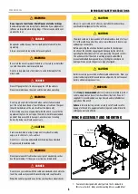
IMpORTANT SAFETY INSTRUCTIONS


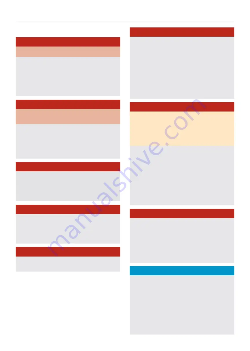
DANGER

DO NOT EXCEED RATED CAPACITY.

INTERMITTENT USE ONLY - COOL BETWEEN USES.
DO NOT

 use winch for lifting/moving people or live animals. 

A minimum of five wraps of cable around the drum barrel is necessary 

for pulling and holding the rated load. The cable clamp is not designed 

to hold the load without the 5 wraps of cable around the drum. 

(usually marked red on the drum end of the cable)


DANGER

Keep yourself and others a SAFE DISTANCE to the side of the cable 

when under tension.

NEVER

 stand or step over a cable, or near a cable under load using a 

winch blanket or sail is strongly recommended.

DON’T

 move the vehicle to pull a load (towing) on the winch cable.  

This could result in cable breakage.

Disconnect 

the remote control and isolate when not in use.


DANGER

DO NOT

 exceed maximum pull rating.  Avoid “shock loading” by using 

the remote lead switch intermittently to take up the slack in the wire 

rope.  “Shock loading” can far exceed the rated capacity for the wire 

rope and drum and will result in damaging winch and brake. By doing 

so will void any warranty.


DANGER

DO NOT 

use you winch as securing device it is not designed for this 

and will result in damaging winch and brake and will void any warranty.

DO NOT 

exceed maximum line pull ratings shown on the tables. 

DO NOT 

use as a hoist.  Do not use for overhead lifting.


DANGER

NEVER 

cut, weld, or modify any part of the winch or cable. By doing 

so will void any warranty


DANGER

When re-spooling the cable

  Ensure that the cable spools in the 

under-wind position with the cable entering the drum from the 

bottom, not the top. To re-spool correctly, and while wearing gloves, 

keep a slight tension on the cable while pushing the remote control 

button to draw in the cable.  Walk toward the winch 

NEVER 

allowing 

the winch cable to slide through your fingers or hands.  

DO NOT

 let your hands get within 12”(30cm) of the winch while re-

spooling.  Turn off the winch and repeat the procedure until a few feet 

of cable is left.  Disconnect the remote control and finish spooling by 

hand by rotating the drum manually with the clutch disengaged.  Keep 

hands clear of the fairlead and drum while the winch is under power.


DANGER

Failure to read and understand these warnings may result in personal 

injury and/or property damage.
Always use gloves to protect hands when handling any type or cable/

rope. Never let the cable slide through your hands.

NEVER

 connect the cable back to itself.

Always apply blocks/chocks/straps to the wheels of the vehicle/

equipment when on an incline and in transportation.
No modifications, alterations, or deviation to the winch are authorized 

by the manufacturer and MUST NOT be made. By doing so will void 

any warranty. 
Duration of winching pulls should be kept as short as possible.  If 

the motor becomes uncomfortably hot to the touch, stop winching 

immediately and let it cool down for approx 8 mins minutes. Do not 

winch for more than two minutes at or near the maximum rated load 

without resting for 8 minutes.


DANGER

If the motor stalls 

DO NOT

 maintain winching.  Winches are designed 

and made for intermittent use and should be used in conjunction with 

their duty cycles.

NEVER

 release the free-spool clutch when there is a load on the 

winch as the load will roll backwards.
Use hand saver hook when handling the hook for spooling or un-

spooling the wire rope.


NOTICE

The winch and its all-derivative types are rated at rated capacity when 

spooling the first rope layer on the drum.  Overloading can damage 

the winch / motor / or wire rope.  
For loads over 70% of rated line pull, we recommend the use of the 

pulley block / snatch block to double the wire rope line and reduce the 

strain.  This will aid in two ways: 
It will reduce the number of rope layers on the drum and reduce the 

load on the wire rope by as much as 50%. When doubling the lineback 

to the vehicle, always attach to the frame or another load bearing 

point..

Summary of Contents for 20SPS12

Page 1: ...ury Specifications descriptions and images in this manual are as accurate as known at the time of publication but are subject to change without notice ENGLISH WINCH MODELS NINJA WINCH OWNERS MANUAL 20...

Page 2: ...galvanized aircraft steel cable or synthetic rope and is designed specifically for load capacity of the rated line pull of this winch The cable feeds on from underneath the drum position it is looped...

Page 3: ...rs or hands DO NOT let your hands get within 12 30cm of the winch while re spooling Turn off the winch and repeat the procedure until a few feet of cable is left Disconnect the remote control and fini...

Page 4: ...be followed to reduce the risk of personal injury and damage to the equipment Read all these instructions before using this tool WARNING Keep children away Children must never be allowed in the work...

Page 5: ...t replace immediately DANGER Do not move your vehicle with the cable extended and attached to the load You could easily exceed the winch rating and snap the cable When the vehicle is parked on an incl...

Page 6: ...ry while making connections 5 Assemble the Clevis Hook to the cable Take off the pin from the Clevis Hook connect the Clevis Hook to the cable and mount the pin back to the Clevis Hook 6 Always use th...

Page 7: ...s directly in front or behind the vehicle or anchor point o Begin winching Be sure that the wire rope is winding evenly and tightly around the drum If needed the vehicle that is being winched can be s...

Page 8: ...to its full length Note how the existing cable is connected to the drum 3 Remove old cable assembly and attach new one as the old cable connected to the drum Insert the end of the new rope and secure...

Page 9: ...hole on the top put the rope on the drum and put the clamp on the rope the hole close to casting plate 3 Press the clamp to the drum and make sure the rope is in the groove of clam Adjust to the same...

Page 10: ...Water has entered motor Allow to drain and dry Run winch until completely dry Motor runs but drum does not turn Clutch not engaged Turn clutch to the In position If problem persists ask a technician t...

Page 11: ...roduct 2 a written description of the problem 3 Buyers name address and contact number 4 copy of the original purchase receipt or BPE Limited can arrange a suitable collection method Charges apply War...

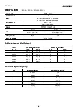
Page 12: ...5 5 Mounting bolt pattern 3 13 79 5 mm 2 M8 Pull Speed Amperes Volts First layer Line Pull Line Speed ft min m min Motor current Amps Max Ibs kgs 12V DC 24V DC 12V DC 24V DC 0 10 5 3 2 11 8 3 6 15 12...

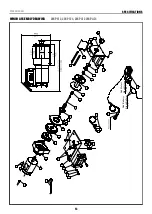
Page 13: ...WINCH ASSEMBLY DRAWING 7 6 4 3 2 1 5 8 32 31 30 28 29 27 25 26 25 26 23 27 24 35 1 96 1 96 5 9 36 Black Battery Red Battery Red Motor Black Motor 33 34 10 9 15 14 12 13 11 17 22 20 21 19 18 16 7 6 20...

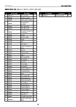
Page 14: ...2 16 K200011 Tie Bar 2 17 K200012 Hex Flange Nut M5 2 18 K200013 Tension Plate 1 19 K200014 Base Plate 1 20 K200015 Clutch Handle 1 21 K200016 Screw M5 x 10 2 22 K200017 Hex Fh Screw M6 x 16 2 23 K20...

Page 15: ...m Net weight Ibs kg 20 5 9 3 16 5 7 5 Mounting bolt pattern 3 13 79 5 mm 2 M8 Pull Speed Amperes Volts First layer Line Pull Line Speed ft min m min Motor current Amps Max Ibs kgS 12V DC 24V DC 12V DC...

Page 16: ...WINCH ASSEMBLY DRAWING 3 17 16 15 13 14 12 10 6 8 9 4 3 5 7 2 1 11 29 7 29 27 28 18 19 20 21 22 23 24 25 26 34 33 35 30 31 32 36 32 31 30 40 41 37 38 39 42 43 7 8 8 25SPS12 25SPS24 25SPA12 25SPA24 35...

Page 17: ...utch axes 1 21 SP0350019 Cam Clutch Gear 1 22 SP0350020 Spring 1 23 SP0350021 Cover Clutch Housing 1 24 SP0350022 Roller Bearing 1 25 SP0350023 Elastic Collar 1 26 SP0350024 Clutch Handle 1 27 SP03500...

Page 18: ...22 0 10 0 18 0 8 2 Mounting bolt pattern 3 13 79 5 mm 2 M8 Item 35SPS 35SPA Pull Speed Amperes Volts First layer Line Pull Line Speed ft min m min Motor current Amps Max Ibs kgs 12V DC 24V DC 12V DC...

Page 19: ...3 0 23 1 10 5 Mounting bolt pattern 5 1 3 78 129mm 96 mm 4 M8 Pull Speed Amperes Volts First layer Line Pull Line Speed ft min m min Current A Ibs kgs 12V DC 24V DC 12V DC 24V DC 0 11 6 3 6 12 5 3 8 2...

Page 20: ...ch Manual SPECIFICATIONS 20 WINCH ASSEMBLY DRAWING 37 36 33 32 31 35 34 3 4 5 6 7 8 9 10 11 12 10 13 14 15 16 17 18 19 20 25 24 23 22 21 2 1 16 26 27 28 30 IN O U T 38 39 45SPS12 45SPS24 45SPA12 45SPA...

Page 21: ...Gear Ring Inner 1 19 X450400 Gear Carrier Assembly Output 1 20 X450500 Gear Carrier Assembly Intermediate 1 21 X450600 Gear Carrier Assembly Input 1 22 X450016 Gear Input Sun 1 23 X450017 Trust Washer...

Page 22: ...75mm Drum size 1 77 3 7 45mm 93 mm Cable 15 64 12 5 6 0mm 3 8m Net Weight kgs 13 0 Mounting bolt pattern 5 1 3 78 129mm 96 mm 4 M8 Pull Speed Amperes Volts First layer Line Pull Line Speed ft min m mi...

Page 23: ...Winch Manual SPECIFICATIONS 23 WINCH ASSEMBLY DRAWING 33 32 3 4 5 6 7 8 9 11 12 13 11 14 15 16 17 18 19 20 21 26 24 23 22 2 1 17 27 29 30 28 35 34 36 37 25 10 31 150HST12 150HST24 250HST12 250HST24...

Page 24: ...Winch Manual SPECIFICATIONS 24 WINCH ASSEMBLY DRAWING 39 40 41 42 43 44 45 46 38 150HST12 150HST24 250HST12 250HST24...

Page 25: ...X450500 Gear Carrier Assembly Intermediate 1 22 X450600 Gear Carrier Assembly Input 1 23 X450017 Gear Input Sun 1 24 X450018 Trust Washer 1 25 X450019 Supporting Block 1 26 X450020 Gear Housing 1 27...

Page 26: ...5mm Drum size 1 77 3 7 45mm 93 mm Cable 15 64 12 5 6 0mm 3 8m Net Weight kgs 13 0 Mounting bolt pattern 5 1 3 78 129mm 96 mm 4 M8 Pull Speed Amperes Volts First layer Line Pull Line Speed ft min m min...

Page 27: ...65mm 128mm Net weight Ibs kg 27 8 12 6 28 9 13 1 28 7 13 0 28 7 13 0 Mounting bolt pattern 5 1 3 76 129mm 96 mm 4 M8 Pull Speed Amperes Volts First layer Line Pull Line Speed ft min m min Current A Ib...

Page 28: ...Winch Manual SPECIFICATIONS 28 WINCH ASSEMBLY DRAWING 36 35 32 31 30 34 33 3 4 5 6 7 8 9 10 11 12 10 13 14 15 16 17 18 19 20 27 26 25 24 23 22 21 2 1 29 16 450HST12 450HST24...

Page 29: ...g 1 16 P450013 Gasket 2 17 P450014 Gear Ring 1 18 P450015 Gear Ring Inner 1 19 P450400 Gear Carrier Assembly Output 1 20 P450500 Gear Carrier Assembly Intermediate 1 21 P450600 Gear Carrier Assembly I...

Page 30: ...et Weight lbs kg 28 7 13 0 Mounting bolt pattern 5 1 3 78 129mm 96 mm 4 M8 Pull Speed Amperes Volts First layer Line Pull Line Speed ft min m min Current A Ibs kgs 12V DC 24V DC 12V DC 24V DC 0 11 8 3...

Page 31: ...Winch Manual SPECIFICATIONS 31 WINCH ASSEMBLY DRAWING 31 30 3 4 5 6 7 8 9 10 11 12 10 13 14 15 16 17 18 19 20 24 23 22 21 2 1 16 29 32 25 27 28 26 33 45EWHST12 45EWHST24...

Page 32: ...w M5 x 45 12 14 X450011 Locking Washer 5 12 15 X450012 End Bearing 1 16 X450013 Gasket 2 17 X450014 Gear Ring 1 18 X450015 Gear Ring Inner 1 19 X450400 Gear Carrier Assembly Output 1 20 X450500 Gear C...

Page 33: ...prechen den Grundanforderungen der relevanten Richtlinien und Normen Dieses Zertifikat ist nur bei den obengenannten Produkten und Konfigurationen im Zusammenhang mit detaillierten Testdaten sowie mit...

Page 34: ...wing Standards BS EN 14492 1 2006 A1 2009 BS EN 60204 1 2018 BS EN ISO 12100 2010 BS EN IEC 61000 6 2 2019 BS EN IEC 61000 4 2 2019 I hereby declare that the equipment named above has been designed an...

Page 35: ...levanten Richtlinien und Normen Dieses Zertifikat ist nur bei den obengenannten Produkten und Konfigurationen im Zusammenhang mit detaillierten Testdaten sowie mit allen zutreffenden rechtlichen Vorsc...

Page 36: ...S EN 60204 1 2018 BS EN ISO 12100 2010 BS EN IEC 61000 6 2 2019 BS EN IEC 61000 4 2 2019 I hereby declare that the equipment named above has been designed and manufactured to comply with relevant sect...

Page 37: ...Q UK service bpeholdings co uk Germany BPE Solutions Deutschland GmbH Altrottstra e 31 D 69190 Walldorf Germany support bpeholdings de France BPE Solutions France SAS 3 Boulevard de Belfort 59000 Lill...

Reviews: