background image

WINCH MANUAL 

OpERATING INSTRUCTIONS

11

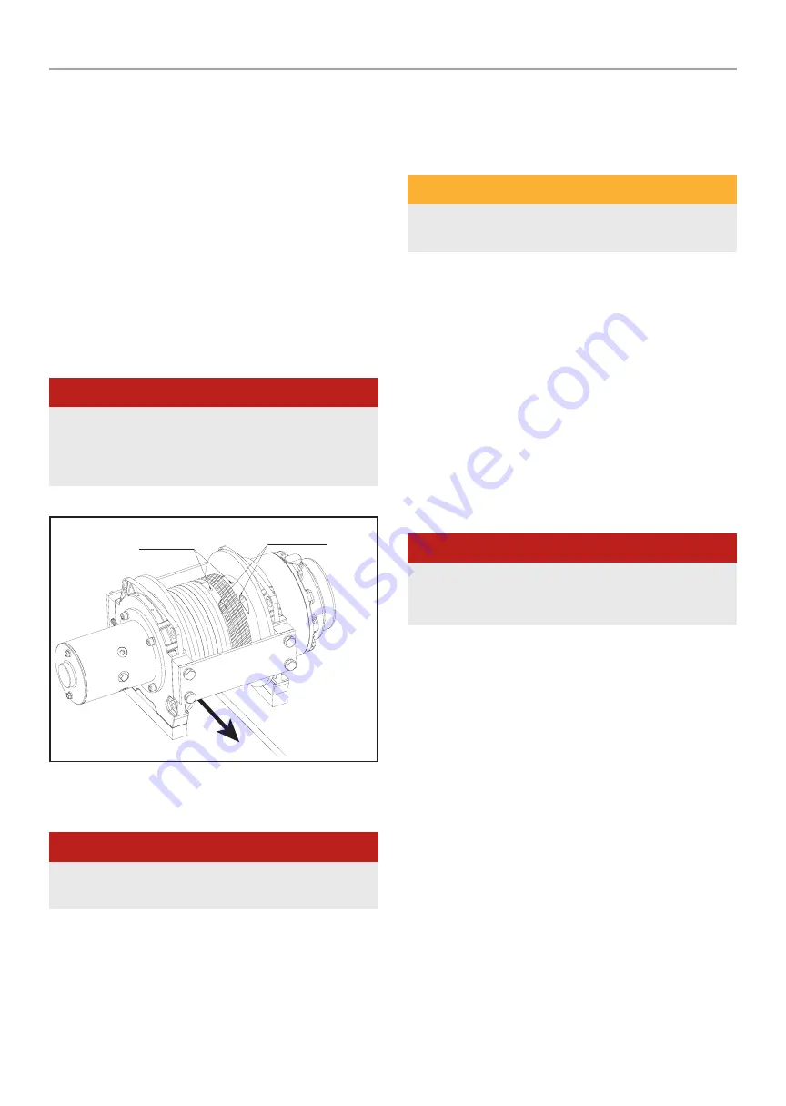
ROpE INSTALLATION

1.  Power-in and/or power-out slightly to align hole in drum to a position 

that is accessible for hoist rope installation.

2.  Disconnect the positive cable from the battery.

3.  Insert the hoist rope around the hoist drum from the bottom and 

through the slot in the drum.

4.  Release drum grub screw(s) located in drum cylinder and slide rope 

through and secure. (On selective models use a loop and wedge 

method to secure).

5.  Ensure the cable does not protrude from the drum surface and that 

the rope is held into place tightly and securely. With end of rope 

installed and secured reconnect power and carefully power-in rope 

evenly onto drum. Keep rope under some sort of tension at all times.


DANGER

A minimum of five wraps of cable around the drum barrel is necessary 

for pulling and holding the rated load. The cable clamp is not designed 

to hold the load without the 5 wraps of cable around the drum. 

(usually marked red on the drum end of the cable)

Spool from underneath drum

Two fastening screws

Pass through two holes

OpERATING INSTRUCTIONS


DANGER

It is important to read ALL instructions and safety information before 

installing and operating your hoist.

1.  Take time to asses your situation and plan your pull.

2.  Inspect mounting structure, hoist, slings and/or accessories for 

signs of wear and damage. Replace any damaged parts.

3.  Know the weight of your load you intend to lift and never exceed your 

hoists rated load.

4.  Connect the remote control lead to the hoist. 

5.  Ensure the load is directly under the hoist, and the rope is not 

tangled or kinked.

6.  Ensure the rope spools in the right direction. 


WARNING

The spoolling direction may accidentally be reversed if rope is run all 

the way out and re-spooled in with control switch in OUT direction.

7.  Ensure the hook latch is functioning properly. Replace damaged 

hook latch before operating hoist.

8.  Double check your anchors and make sure all connections are 

secure.

9.  Inspect the wire rope.  Make sure there are at least 5 wraps of wire 

rope around the hoist drum.(usually marked with red)

10.  Clear the area.  Make sure all people, spectators are well back.
11.  Begin hoisting.  Be sure that the wire rope is winding evenly and 

tightly around the drum. Avoid shock loading the wire rope under 

tension.

12.  The hoist is meant for intermittent use.  Under full load with a single 

line rig do not power in for more than 8 minutes without letting the 

motor cool down for a few minutes and then resume the hoisting 

operation.


DANGER

NEVER allow a crane to “two block.” Excess loads can create 

undetectable damage, which may cause the hoist to fail even when 

lifting loads within its rated capacity..

13.  Once the load is secure - Release the tension and disconnect the 

hook from the load. The hoist is NOT designed as securing device 

and should NEVER hold a suspending load or used as securing device 

whilst in transport, hoist cable MUST be released when equipment 

is secure. Failure to follow these instructions will damage the brake 

and hoist and void any warranty.

14.  Rewind the wire rope under load.  Make sure that any wire already 

on the drum has spooled tightly and neatly.  If not, draw out the wire 

and re-spool from the point where the rope is tight.

15.  Keep your hands clear of the hoist drum as the wire rope is being 

drawn in.

16.  Disconnect the remote control lead and store in a clean, dry place.
17.  Clean and inspect connections and mounting hardware for next 

hoisting operation.

Summary of Contents for EH800-CAD

Page 1: ...e to do so could result in serious injury Specifications descriptions and images in this manual are as accurate as known at the time of publication but are subject to change without notice ENGLISH HOI...

Page 2: ...a powerful piece of machinery It is important that you understand the basics of its operation and specifications so that when you need to use it you can safely use it with confidence Below is a list...

Page 3: ...mittent use and should be used in conjunction with their duty cycles NOTICE The hoist and its all derivative types are rated at rated capacity when spooling the first rope layer on the drum Overloadin...

Page 4: ...parts that appear worn or damaged should be carefully checked to determine that it will operate properly and perform to its intended function Check for damage including alignments binding of moving pa...

Page 5: ...y objects attached WARNING Stop the hoist if you hear strange noises and vibrations emitting from the gearbox WARNING Ensure that the load being lifted is well balanced and secured before starting WAR...

Page 6: ...e sure to fix a rope in the center of swivel hook HOIST ASSEMBLY AND MOUNTING 1 Make sure that the mounting structure can withstand the full rated lift of the hoist 2 Ensure that the hoist frame will...

Page 7: ...ual Hoist ASSEMBLY AND MOUNTING 7 Models EH800 CAD EH1000 CAD EH1000 SD CAD EH800 CAD EH1000 CAD EH1000 EH1000SD CAD EH1000SG Models EH1200 CAD EH160 CAD0 EH2000 CAD EH1200 CAD EH1200 EH1600 EH2000 CA...

Page 8: ...s turning and releasing cable then your connections are accurate If the drum is turning and collecting more cable then reverse the leads on the motor Repeat and check rotation MOUNT CONTACTOR OPTIONAL...

Page 9: ...1 5 M 6 m 5 20 ft 1 Gauge Over 6 m 20 ft 0 Gauge 4 Minimize cable length where possible 5 Plan the route for your electrical cords Make sure to check that the cables and ground wire can be routed to...

Page 10: ...res fixed together Green Yellow Yellow Red Red Models EH2500 CAD EH3000 CAD EH4000 CAD F1 F2 A Black Black Black 3 black wires fixed together Green Yellow Yellow Red Red Models EH800 CAD EH1000 CAD EH...

Page 11: ...the right direction WARNING The spoolling direction may accidentally be reversed if rope is run all the way out and re spooled in with control switch in OUT direction 7 Ensure the hook latch is functi...

Page 12: ...semble the gear box Repairs should be done by the manufacturer or an authorized repair center 3 The gear box has been lubricated using a high temperature lithium grease and is sealed at the factory No...

Page 13: ...an and tighten Repair or replace switch assembly Motor tries to powerout but hoist stalls or locks up Load brake failure Service or replace load brake Hoist operates in both directions but will not li...

Page 14: ...the Product 2 a written description of the problem 3 Buyers name address and contact number 4 copy of the original purchase receipt or BPE Solutions North America can arrange a suitable collection me...

Page 15: ...Mounting bolt pattern 4 89 3 0 124mm 76 2 mm Overall dimensions 14 5 4 92 5 1 368 mm 125 mm 129 mm LIFT SPEED AMPS VOLTS First layer Line Pull Line Speed ft min m min Current A lbs kgs 12v DC 12v DC 0...

Page 16: ...lt pattern 6 6 3 0 168mm 76 2 mm Overall dimensions 16 2 4 92 5 1 412 mm 125 mm 129 mm LIFT SPEED AMPS VOLTS First layer Line Pull Line Speed ft min m min Current A lbs kgs 12v DC 12v DC 0 18 5 5 28 5...

Page 17: ...bolt pattern 4 89 3 0 124mm 76 2 mm Overall dimensions 14 5 4 92 5 1 368 mm 125 mm 129 mm LIFT SPEED AMPS VOLTS First layer Line Pull Line Speed ft min m min Current A lbs kgs 12v DC 12v DC 0 18 5 5...

Page 18: ...n 4 4 5 102mm 114 3 mm Overall dimensions 16 73 6 3 6 6 425 mm 160 mm 167 mm LIFT SPEED AMPS VOLTS First layer Line Pull Line Speed ft min m min Current A lbs kgs 12v DC 12v DC 0 28 2 8 6 58 300 136 2...

Page 19: ...mm 6 6 5 152mm 165 1mm Overall dimensions 18 5 8 43 8 6 469 mm 214mm 218mm LIFT SPEED AMPS VOLTS First layer Line Pull Line Speed ft min m min Current A lbs kgs 12v DC 12v DC 0 19 7 6 75 400 181 18 3...

Page 20: ...52mm 165 1mm Overall dimensions 18 5 8 43 8 6 469 mm 214mm 218mm LIFT SPEED AMPS VOLTS First layer Line Pull Line Speed ft min m min Current A lbs kgs 12v DC 12v DC 0 19 7 6 75 400 181 18 3 5 6 80 800...

Page 21: ...6 73 6 5 171mm 165 1mm Overall dimensions 19 2 10 5 9 25 488 mm 267mm 235mm LIFT SPEED AMPS VOLTS First layer Line Pull Line Speed ft min m min Current A lbs kgs 12v DC 12v DC 0 24 6 7 5 75 1000 454...

Page 22: ...5 203mm 114 3 mm 8 6 5 203mm 165 1mm Overall dimensions 20 5 10 5 9 25 520 mm 267mm 235mm LIFT SPEED AMPS VOLTS First layer Line Pull Line Speed ft min m min Current A lbs kgs 12v DC 12v DC 0 24 9 7...

Page 23: ...5 203mm 114 3 mm 8 6 5 203mm 165 1mm Overall dimensions 20 5 11 7 10 4 520 mm 297mm 264mm LIFT SPEED AMPS VOLTS First layer Line Pull Line Speed ft min m min Current A lbs kgs 12v DC 12v DC 0 29 5 9 0...

Page 24: ...Winch Manual EH800 Exploded Diagram 24 EH800 EXPLODED DIAGRAM...

Page 25: ...1 Screw M4 x35 19 H080017 1 Ring Seals 20 H080018 1 End Bearing 21 H080019 1 Gasket 22 H080020 1 Hexagonal Shaft 23 H080021 1 Gear Ring 24 H080300 1 Gear Carrier Assembly Output 25 H080400 1 Gear Carr...

Page 26: ...Winch Manual EH1000 Exploded Diagram 26 EH1000 EXPLODED DIAGRAM...

Page 27: ...1 Screw M4 x35 19 H100017 1 Ring Seals 20 H100018 1 End Bearing 21 H100019 1 Gasket 22 H100020 1 Hexagonal Shaft 23 H100021 1 Gear Ring 24 H100300 1 Gear Carrier Assembly Output 25 H100400 1 Gear Car...

Page 28: ...Winch Manual EH1000 SD Exploded Diagram 28 EH1000 SD EXPLODED DIAGRAM...

Page 29: ...Screw M4 x35 19 H10SD0017 1 Ring Seals 20 H10SD0018 1 End Bearing 21 H10SD0019 1 Gasket 22 H10SD0020 1 Hexagonal Shaft 23 H10SD0021 1 Gear Ring 24 H10SD0300 1 Gear Carrier Assembly Output 25 H10SD0400...

Page 30: ...Winch Manual EH1200 Exploded Diagram 30 EH1200 EXPLODED DIAGRAM...

Page 31: ...120014 2 Tie Bar 17 H120300 1 Drum Assembly 18 H120015 2 Screw M8 10 19 H120016 1 End Bearing 20 H120017 2 Gasket 21 H120018 1 Gear Ring 22 H120019 1 Circlip For Hole 23 H120020 1 Bearing 24 H120400 1...

Page 32: ...Winch Manual EH1600 Exploded Diagram 32 EH1600 EXPLODED DIAGRAM...

Page 33: ...2 3 Tie bar 16 H160013 10 Screw M8 x 75 17 H160014 10 Lock Washer 8 18 H160015 1 End Bearing 19 H160016 2 Gasket 20 H160017 1 Gear Ring Output 21 H160400 1 Gear Carrier Assembly Output 22 H160018 1 Ci...

Page 34: ...Winch Manual EH2000 Exploded Diagram 34 EH2000 EXPLODED DIAGRAM...

Page 35: ...3 Tie bar 16 H200013 10 Screw M8 x 75 17 H200014 10 Lock Washer 8 18 H200015 1 End Bearing 19 H200016 2 Gasket 20 H200017 1 Gear Ring Output 21 H200400 1 Gear Carrier Assembly Output 22 H200018 1 Cir...

Page 36: ...Winch Manual EH2500 Exploded Diagram 36 EH2500 EXPLODED DIAGRAM...

Page 37: ...17 H250014 1 Stand bar a 18 H250015 10 Screw M8 x 75 19 H250016 10 Lock Washer 8 20 H250017 1 End Bearing 21 H250018 2 Gasket 22 H250019 1 Gear Ring Output 23 H250400 1 Gear Carrier Assembly Output 24...

Page 38: ...Winch Manual EH3000 Exploded Diagram 38 EH3000 EXPLODED DIAGRAM...

Page 39: ...17 H300014 1 Stand bar a 18 H300015 10 Screw M8 x 75 19 H300016 10 Lock Washer 8 20 H300017 1 End Bearing 21 H300018 2 Gasket 22 H300019 1 Gear Ring Output 23 H300400 1 Gear Carrier Assembly Output 24...

Page 40: ...Winch Manual EH4000 Exploded Diagram 40 EH4000 EXPLODED DIAGRAM...

Page 41: ...17 H400014 1 Stand bar a 18 H400015 10 Screw M8 x 75 19 H400016 10 Lock Washer 8 20 H400017 1 End Bearing 21 H400018 2 Gasket 22 H400019 1 Gear Ring Output 23 H400400 1 Gear Carrier Assembly Output 24...

Page 42: ...support warriorwinches com For warranty and repair enquiries please contact the retailer where you purchased your hoist product...

Reviews: