6.3.3.7
Sludge tank (1T05)
The sludge tank should be located directly beneath the separators, or as close as possible
below the separators, unless it is integrated in the separator unit. The sludge pipe must be
continuously falling.
6.3.4
Fuel feed system - MDF installations
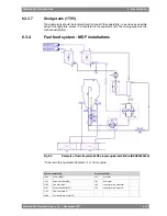
Fig 6-5
Example of fuel oil system, MDF, single engine installation (DAAE022042b)
* To be remotely operated if located < 5 m from engine.
Pipe connections
System components
Fuel inlet
101
Cooler (MDF)
1E04
Fuel outlet
102
Automatic filter (MDF)
1F04
Leak fuel drain, clean fuel
103
Fine filter (MDF)
1F05
Leak fuel drain, dirty fuel
104
Suction strainer (MDF)
1F07
Flow meter (MDF)
1I03
Fuel feed pump unit (MDF)
1N08
Wärtsilä 46F Product Guide - a19 - 1 December 2017
6-13
6. Fuel Oil System
Wärtsilä 46F Product Guide
Summary of Contents for 12V46F
Page 1: ...PRODUCT GUIDE Wärtsilä 46F ...
Page 44: ...This page intentionally left blank ...
Page 52: ...This page intentionally left blank ...
Page 78: ...This page intentionally left blank ...
Page 102: ...This page intentionally left blank ...
Page 124: ...This page intentionally left blank ...
Page 144: ...This page intentionally left blank ...
Page 162: ...This page intentionally left blank ...
Page 186: ...This page intentionally left blank ...
Page 192: ...This page intentionally left blank ...
Page 194: ...This page intentionally left blank ...
Page 197: ......
Page 198: ......
Page 199: ......


