background image


Page | 107 
 

14.4.1.7  Stand-by pump, LT cooling water (if applicable) (4P05) 

 
The engine control system starts the pump automatically via a motor starter, if the cooling water 

pressure drops below a preset level when the engine is running. 


14.4.1.8  Circulating pump for preheater (4P04) 
 

The preheater pump shall start when the engine stops (to ensure water circulation through the 

hot engine) and stop when the engine starts. The engine control system handles start/stop of 
the pump automatically. 


14.5 

System  requirements  and  guidelines  for  gas-electric 

propulsion 

 
Typical features to be incorporated in the propulsion control and power management systems 

in a gas-electric ship: 


1. The load increase program must limit the load increase rate during ship acceleration and 

load transfer between generators according to the curves in chapter 

2.2 Loading Capacity


Continuously active limit: “normal max. loading in operating condition”. 


During the first 6 minutes after starting an engine: “preheated engine” 

 
If the control system has only one load increase ramp, then the ramp for a preheated engine 

is to be used. 

 
The load increase rate of a recently connected generator is the sum of the load transfer 

performed  by  the  power  management  system  and  the  load  increase  performed  by  the 
propulsion  control,  if  the  load  sharing  is  based  on  speed  droop.  In  a  system  with 
isochronous load sharing the loading rate of a recently connected generator is not affected 
by changes in the total system load (as long as the generators already sharing load equally 
are not loaded over 100%). 

 
2. 


Rapid loading according to the “emergency” curve in chapter 

2.2 Loading Capacity 

may 

only be possible by activating an emergency function, which generates visual and audible 
alarms in the control room and on the bridge.


3.  The propulsion control should be able to control the propulsion power according to the 

load increase rate at the gas generators. Controlled load increase with different number of 
generators connected and in different operating conditions is difficult to achieve with only 
time ramps for the propeller speed. 


4.  The load reduction rate should also be limited in normal operation. Crash stop can be 

recognised by for example a large lever movement from ahead to astern. 


5. The power management system performs loading and unloading of generators in a speed 

droop  system,  and  it  usually  also  corrects  the  system  frequency  to  compensate  for  the 
droop offset, by adjusting the speed setting of the individual speed control units. The speed 
reference  is  adjusted  by  sending  an  increase/decrease  pulse  of  a  certain  length  to  the 
speed  control  unit.  The  power  management  should  determine  the  length  of  the 
increase/decrease pulse based on the size of the desired correction and then wait for 30 
seconds or more before performing a new correction, in particular when performing small 
corrections. 


The relation between duration of increase/decrease signal and change in speed reference 

is usually 0.1 Hz per second. The actual speed and/or load will change at a slower rate. 

 
6.  The  full  output  of  the  generator  is  in  principle  available  as  soon  as  the  generator  is 

connected  to  the  network,  but  only  if  there  is  no  power  limitation  controlling  the  power 

Summary of Contents for 31SG

Page 1: ...Page 1 PRODUCT GUIDE W rtsil 31SG...

Page 2: ...REGULAR IMPROVEMENTS MODIFICATIONS AND CHANGES CONSEQUENTLY THE PUBLISHER AND COPYRIGHT OWNER OF THIS PUBLICATION CAN NOT ACCEPT ANY RESPONSIBILITY OR LIABILITY FOR ANY EVENTUAL ERRORS OR OMISSIONS IN...

Page 3: ...specific instructions for planning the installation are always delivered Any data and information herein is subject to revision without notice Issue Published Updates 9 2019 n a First Version 9 2019...

Page 4: ...Page 4 This page intentionally left blank...

Page 5: ...rtsil 14V31SG 32 3 6 W rtsil 16V31SG 35 4 Description of the Engine 38 4 1 Definitions 38 4 2 Main components and systems 38 4 3 Time between Inspection or Overhaul Expected Life Time 42 4 4 Engine st...

Page 6: ...engine exhaust components 99 13 2 Marine exhaust emissions legislation 99 13 3 Methods to reduce exhaust emissions 99 14 Automation System 100 14 1 Technical data and system overview 100 14 2 Function...

Page 7: ...ls 121 18 4 Required deck area for service work 121 19 Transport Dimensions and Weights 125 19 1 Lifting of generating sets 125 19 2 Engine components 126 20 Product Guide Attachments 128 21 ANNEX 130...

Page 8: ...Page 8 This page intentionally left blank...

Page 9: ...1 Maximum continuous output Table 1 1 Rating table for W rtsil 31SG The mean effective pressure Pe can be calculated as follows where Pe mean effective pressure bar P output per cylinder kW n engine...

Page 10: ...etric pressure 100 kPa air temperature 25 C relative humidity 30 charge air coolant temperature 25 C Correction factors for the fuel oil consumption in other ambient conditions are given in standard I...

Page 11: ...6 W 8V31SG 6087 6196 3560 1650 1650 877 986 300 500 500 W 10V31SG 6726 6836 4200 1650 1650 877 986 300 500 500 Engine H1 H1 H2 H3 H4 W1 W1 W2 W3 W4 W5 W5 Weight Engine Weight liquids W 8V31SG 3205 320...

Page 12: ...8730 5480 2000 2000 1000 1250 300 908 908 W 16V31SG 9120 9370 9120 2000 2000 1000 1250 300 908 908 Engine H1 H1 H2 H3 H4 W1 W2 W3 W4 W5 Weight Engine Weight liquids W 12V31SG 2926 2926 4633 1496 650...

Page 13: ...t without liquids damper and flywheel as a rule of thumb add 60kg per cylinder on top of 8 and or 10V engine weight or add 50kg per cylinder for 12 14 and 16V engines for additional gas components wei...

Page 14: ...Page 14 This page intentionally left blank...

Page 15: ...acity Controlled load increase is essential for highly supercharged engines as the turbocharger needs time to accelerate before it can deliver the required amount of air A slower loading ramp than the...

Page 16: ...oading rate Engine load of MCR Nominal loading s Fast loading MN70 s Fast loading MN80 s Emergency Hybrid operation only s 0 0 0 0 0 100 300 90 70 20 Fig 2 1 Normal Loading rate constant speed engines...

Page 17: ...he propulsion control The emergency curve is close to the maximum capability of the system and it shall not be used as the normal limit for the engine In dynamic positioning applications loading ramps...

Page 18: ...hich has been operated at above 30 load within the last 30 minutes If higher load step capability is required then the dimensioning of the Energy Storage System needs to be applied Following Hybrid lo...

Page 19: ...ive low load operation should not exceed the recommended values given in the chart and table The time is reset after a cleaning run at minimum 70 load for a minimum of 1 hour If recommended time limit...

Page 20: ...d generator Maximum 10 minutes if the engine is to be stopped after the idling 3 5 minutes idling before stop is recommended Maximum 8 hours if the engine is to be loaded after the idling NOTE Operati...

Page 21: ...Page 21 This page intentionally left blank...

Page 22: ...n the respective chapter 3 1 1 Engine driven pumps The fuel consumption stated in the technical data tables is with engine driven pumps The increase in fuel consumption with engine driven pumps is giv...

Page 23: ...r turbocharger at 100 load TE 517 C 344 346 300 346 Temperature after turbocharger at 85 load TE 517 C 360 362 350 362 Temperature after turbocharger at 75 load TE 517 C 375 377 350 377 Temperature af...

Page 24: ...Oil volume in turning device l 9 0 11 0 9 0 11 0 9 0 11 0 9 0 11 0 Cooling water system HT cooling water system Pressure at engine after pump nom PT 401 kPa 358 static 358 static 358 static 358 stati...

Page 25: ...ng to ISO 15550 except for LT water temperature which is corresponding to charge air receiver temperature 55 C in gas operation with engine driven water and lubricating oil pumps Tolerance for cooling...

Page 26: ...4 6 4 5 4 6 Temperature after turbocharger at 100 load TE 517 C 344 346 344 346 Temperature after turbocharger at 85 load TE 517 C 360 362 360 362 Temperature after turbocharger at 75 load TE 517 C 3...

Page 27: ...se ventilation backpressure max kPa 0 1 0 1 0 1 0 1 Oil volume in turning device l 9 0 11 0 9 0 11 0 9 0 11 0 9 0 11 0 Cooling water system HT cooling water system Pressure at engine after pump nom PT...

Page 28: ...conditions according to ISO 15550 except for LT water temperature which is corresponding to charge air receiver temperature 55 C in gas operation with engine driven water and lubricating oil pumps To...

Page 29: ...turbocharger at 100 load TE 517 C 344 346 344 346 Temperature after turbocharger at 85 load TE 517 C 360 362 360 362 Temperature after turbocharger at 75 load TE 517 C 375 377 375 377 Temperature aft...

Page 30: ...Oil volume in turning device l 9 0 11 0 9 0 11 0 9 0 11 0 9 0 11 0 Cooling water system HT cooling water system Pressure at engine after pump nom PT 401 kPa 363 static 363 static 363 static 363 stati...

Page 31: ...ng to ISO 15550 except for LT water temperature which is corresponding to charge air receiver temperature 55 C in gas operation with engine driven water and lubricating oil pumps Tolerance for cooling...

Page 32: ...ter turbocharger at 100 load TE 517 C 344 346 344 346 Temperature after turbocharger at 85 load TE 517 C 360 362 360 362 Temperature after turbocharger at 75 load TE 517 C 375 377 375 377 Temperature...

Page 33: ...il volume in turning device l 9 0 11 0 9 0 11 0 9 0 11 0 9 0 11 0 Cooling water system HT cooling water system Pressure at engine after pump nom PT 401 kPa 398 static 398 static 398 static 398 static...

Page 34: ...ng to ISO 15550 except for LT water temperature which is corresponding to charge air receiver temperature 55 C in gas operation with engine driven water and lubricating oil pumps Tolerance for cooling...

Page 35: ...ter turbocharger at 100 load TE 517 C 344 346 344 346 Temperature after turbocharger at 85 load TE 517 C 360 362 360 362 Temperature after turbocharger at 75 load TE 517 C 375 377 375 377 Temperature...

Page 36: ...volume in turning device l 9 0 11 0 9 0 11 0 9 0 11 0 9 0 11 0 Cooling water system HT cooling water system Pressure at engine after pump nom PT 401 kPa 373 static 373 static 373 static 373 static Pr...

Page 37: ...ng to ISO 15550 except for LT water temperature which is corresponding to charge air receiver temperature 55 C in gas operation with engine driven water and lubricating oil pumps Tolerance for cooling...

Page 38: ...screws at the lower guiding provide a very rigid crankshaft bearing assembly A hydraulic jack supported in the oil sump offers the possibility to lower and lift the main bearing caps e g when inspect...

Page 39: ...luence on the bearing function A wireless system for real time temperature monitoring of connecting rod big end bearings BEB monitoring system is as standard 4 2 5 Cylinder liner The cylinder liners a...

Page 40: ...st of the components in the valve mechanism 4 2 10 Camshaft drive The camshafts are driven by the crankshaft through a gear train 4 2 11 Turbocharging and charge air cooling The selected 2 stage turbo...

Page 41: ...w pressure 2 stage charge air cooler The LT water is cooling the lubricating oil cooler the second stage of the low pressure 2 stage charge air cooler and the high pressure 1 stage charge air cooler F...

Page 42: ...s less than 75 Based on the fuel quality intermediate mechanical cleaning might be necessary Component Time between inspection or overhaul h Expected lifetime Gas Operation Gas Operation Piston 32000...

Page 43: ...Page 43 This page intentionally left blank...

Page 44: ...ollowing aspects shall be taken into consideration Pockets shall be avoided When not possible drain plugs and air vents shall be installed Vent pipes shall be continuously rising Flanged connections s...

Page 45: ...high in terms of their effect on pressure drop In longer supply lines it is often necessary to restrict velocities to 15 m s to limit the pressure drop Pipeline sizing on pressure drop As a rule of th...

Page 46: ...ferent classes DNV GL or groups ABS depending on pressure temperature and media The pipe class can determine Type of connections to be used Heat treatment Welding procedure Test method Systems with hi...

Page 47: ...ed to be clean before lifting it onboard for installation During the construction time uncompleted piping systems shall be maintained clean Open pipe ends should be temporarily closed Possible debris...

Page 48: ...be approved in all work phases after completed pickling 5 8 Flexible pipe connections All external pipes must be precisely aligned to the fitting or the flange of the engine to minimize causing exter...

Page 49: ...Page 49 Fig 5 1 Flexible hoses...

Page 50: ...ndation The first support should be located as close as possible to the flexible connection Next support should be 0 3 0 5 m from the first support First three supports closest to the engine or genera...

Page 51: ...Page 51 Fig 5 3 Flange supports of flexible pipe connections 4V60L0796 Fig 5 4 Pipe clamp for fixed support 4V61H0842...

Page 52: ...Page 52 This page intentionally left blank...

Page 53: ...e EN 16726 2015 standard shall be used Additionally W rtsil has developed an MN calculator 2 Hydrogen content higher than 3 volume has to be considered project specifically 3 In the specified operatin...

Page 54: ...es are solenoid operated and electronically controlled whereas pre chamber is hydro mechanically controlled with sparkplug 6 3 Fuel gas system 6 3 1 External fuel gas system 6 3 1 1 Fuel gas system wi...

Page 55: ...s system with enclosed GVU Fig 6 2 Example of fuel gas system with enclosed GVU DAAF077105B System components Supplier 01 Gas detector 02 Gas double wall system ventilation fan 10N05 Gas valve unit 10...

Page 56: ...lose to the tank connection space The ventilation air is taken from both inlets and lead through the annular space of the double wall pipe to the GVU room or to the enclosure of the gas valve unit Fro...

Page 57: ...upply to the engine on request The solenoid operated venting valve in the double block and bleed function will relief the pressure trapped between the block valves after closing of the block valves Th...

Page 58: ...Page 58 Fig 6 4 Gas valve unit reference P I diagram DAAF051037D...

Page 59: ...Page 59 Fig 6 5 Main dimensions of the enclosed GVU DAAF060741A Fig 6 6 Main dimensions of the open GVU DAAW010186A...

Page 60: ...Page 60 Fig 6 7 Gas valve unit P I diagram open type DAAF085795A...

Page 61: ...nition Alternatively to ventilating outside into the atmosphere other means of disposal e g a suitable furnace can also be considered However this kind of arrangement has to be accepted by classificat...

Page 62: ...indicate when the crankcase have been flushed from toxic gases 3 Crankcase size 0 9 m3 crank v engine 6 3 1 8 Gas feed pressure The required fuel gas feed pressure depends on the expected minimum low...

Page 63: ...of deposit formation preignition and knocking while too low ash content can lead to increased exhaust valve valve seat wear Low ash lubricating oils to be used have typically sulphated ash content of...

Page 64: ...Page 64 Fig 7 2 Lubricating oil system single engine wet sump DAAF301501B...

Page 65: ...Page 65 Fig 7 3 Lubricating oil system Gas multiple engines wet sump DAAF301500A...

Page 66: ...long stop must be taken into account when dimensioning the electric motor Separator preheater 2E02 The preheater is to be dimensioned according to the feed pump capacity and the temperature in the sys...

Page 67: ...stated in chapter Technical data The pipe connection between the engine oil sump and the system oil tank must be flexible to prevent damages due to thermal expansion The return pipes from the engine o...

Page 68: ...e The suction strainer and the suction pipe must be amply dimensioned to minimize pressure losses The suction strainer should always be provided with alarm for high differential pressure Design data F...

Page 69: ...acity see Technical data Design pressure max 0 8 MPa 8 bar Design temperature max 100 C Lubricating oil viscosity SAE 40 Viscosity for dimensioning the electric 500 mm2 s cSt motor 7 3 Crankcase venti...

Page 70: ...f the piping and equipment built on the engine is not required and flushing oil shall not be pumped through the engine oil system which is flushed and clean from the factory It is however acceptable t...

Page 71: ...arate flushing oil which has an ideal viscosity in ambient temperature 7 4 3 2 Flushing with engine oil The ideal is to use engine oil for flushing This requires however that the separator unit is in...

Page 72: ...Page 72 This page intentionally left blank...

Page 73: ...ification Design pressure 1 MPa 10 bar Nominal pressure 0 7 MPa 7 bar Dew point temperature 3 C Max oil content 1 mg m3 Max particle size 3 m 8 2 External compressed air system The design of the start...

Page 74: ...nding on the operation conditions of the installation an oil and water separator may be needed in the pipe between the air vessel and the engine 8 2 3 Starting air vessel 3T01 The starting air vessels...

Page 75: ...arting air vessel volume m3 pE normal barometric pressure NTP condition 0 1 MPa VE air consumption per start Nm3 See Technical data n required number of starts according to the classification society...

Page 76: ...dosage and further instructions 9 1 2 Glycol Use of glycol in the cooling water is not recommended unless it is absolutely necessary Glycol raises the charge air temperature which may require de ratin...

Page 77: ...Page 77 Fig 9 1 Example diagram for multiple main engines DAAF301505A...

Page 78: ...e combustion air can be below zero degrees Celsius after the compressor stage it cools down the cooling water and the engine instead of releasing heat to the cooling water in the charge air cooler If...

Page 79: ...perature control of the LT water by increasing the seawater temperature 9 2 2 Stand by circulation pumps 4P03 4P05 Stand by pumps should be of centrifugal type and electrically driven Required capacit...

Page 80: ...w to the fresh water cooler must be calculated case by case based on how the circuit is designed In case the fresh water central cooler is used for combined LT and HT water flows in a parallel system...

Page 81: ...ufficient static pressure for the circulating pumps Design data Volume min 10 of the total system volume Concerning the water volume in the engine see chapter Technical data The expansion tank should...

Page 82: ...mbination of both In all cases a separate circulating pump must be used It is common to use the heat from running auxiliary engines for preheating of main engines In installations with several main en...

Page 83: ...it can be supplied The unit comprises Electric or steam heaters Circulating pump Control cabinet for heaters and pump Set of thermometers Non return valve Safety valve 9 2 13 Throttles Throttles orifi...

Page 84: ...ir exchanges hour has to be fulfilled is then calculated using the formula where qv air flow m s total heat emission to be evacuated kW air density 1 13 kg m c specific heat capacity of the ventilatio...

Page 85: ...tion air is taken from the engine room through a filter on the turbocharger This reduces the risk for too low temperatures and contamination of the combustion air It is important that the combustion a...

Page 86: ...flap to take the air from the engine room or from outside depending on engine load and air temperature For very cold conditions arctic setup is to be used The combustion air fan is stopped during star...

Page 87: ...Page 87 This page intentionally left blank...

Page 88: ...10V31 DAAF343596A Fig 11 2 Exhaust pipe connections W12V W16V31 DAAF343596A NOTE Pipe Connection 501 Exhaust Gas Outlet DIN86044 PN 6 Engine TC Location Free end Driving end W 8V31SG 0 45 90 0 45 90 W...

Page 89: ...pipe into open air Backpressure thermal expansion and supporting are some of the decisive design factors Flexible bellows must be installed directly on the turbocharger outlet to compensate for therma...

Page 90: ...will be safely directed through predefined routes The following guidelines should be observed when designing the external exhaust system The piping and all other components in the exhaust system shoul...

Page 91: ...xhaust system Outlets are to discharge to a safe place remote from any source of ignition The number and location of explosion relief devices shall be such that the pressure rise caused by a possible...

Page 92: ...s very important that the exhaust pipe is properly fixed to a support that is rigid in all directions directly after the bellows on the turbocharger There should be a fixing point on both sides of the...

Page 93: ...on the engine in order to keep the exhaust gas temperature and backpressure into SCR unit working range The exhaust gas piping must be straight at least 3 5 meters in front of the SCR unit If both an...

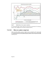
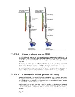
Page 94: ...d to cover the whole frequency spectrum 11 2 10 2 Silencer system comparison With a conventional silencer system the design of the noise reduction system usually starts from the engine With the CSS th...

Page 95: ...to a exhaust gas flow velocity of max 40 m s The pressure drop of a CSS element is lower compared to a conventional exhaust gas silencer 5R02 11 2 10 4 Conventional exhaust gas silencer 5R02 Yard des...

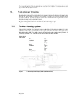
Page 96: ...eration manual must be carefully followed Regular cleaning of the turbine is not necessary when operating on gas 12 1 Turbine cleaning system A dosing unit consisting of a flow meter and an adjustable...

Page 97: ...Page 97 12 2 Compressor cleaning system The compressor side of the turbocharger is cleaned with the same equipment as the turbine...

Page 98: ...Page 98...

Page 99: ...ich represents the first set of regulations on the marine exhaust emissions The IMO Tier 3 NOx emission standard was entered into force from year 2016 It will by then apply for new marine diesel engin...

Page 100: ...ms 14 1 Technical data and system overview 14 1 1 Ingress protection The ingress protection class of the system is IP54 if not otherwise mentioned for specific modules 14 1 2 Ambient temp for automati...

Page 101: ...nd instrumentation are prewired on the engine 14 1 3 Local operator panel The Local operator panel LOP consist of a display unit LDU with touch screen and pushbuttons as well as an emergency stop butt...

Page 102: ...ower unit supplies DC power to the automation system on the engine and provides isolation from other power supply systems onboard The cabinet is designed for bulkhead mounting protection degree IP44 m...

Page 103: ...x Ethernet CAT5 Gas ValveUnit Integrated Automation System I 4 x 2 x 0 75 mm2 2 x 2 x 0 75 mm2 3 x 2 x 0 75 mm2 Engine Gas ValveUnit I 4 x 2 x 0 75 mm2 Gas ValveUnit Fuel gas supply system I 1 x 2 x 0...

Page 104: ...s started and engine speed is raised to nominal The start mode is interrupted in case of abnormalities during the start sequence The start sequence takes about 1 5 minutes to complete 14 2 3 Stop shut...

Page 105: ...d speed reference will share load equally Loading and unloading of a generator is accomplished by adjusting the speed reference of the individual speed control unit The speed droop is typically 4 whic...

Page 106: ...3 x 400 50 15 0 28 4 3 x 440 60 15 0 25 7 14 4 1 3 Exhaust gas ventilation unit The exhaust gas ventilating unit is engine specific and includes an electric driven fan flow switch and closing valve F...

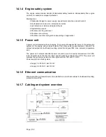
Page 107: ...sharing load equally are not loaded over 100 2 Rapid loading according to the emergency curve in chapter 2 2 Loading Capacity may only be possible by activating an emergency function which generates...

Page 108: ...pacity the recently connected generator will continue to pick up load according to the speed droop curve Also in isochronous load sharing mode a generator still on the loading ramp will start to pick...

Page 109: ...Page 109 This page intentionally left blank...

Page 110: ...the ship and also serve to protect the generating set bearings from possible fretting caused by hull vibration The number of mounts and their location is calculated to avoid resonance with excitation...

Page 111: ...in the mounts is natural rubber and it must therefore be protected from oil oily water and fuel The mounts should be evenly loaded when the generating set is resting on the mounts The maximum permiss...

Page 112: ...When installing the flexible pipe connections unnecessary bending or stretching should be avoided The external pipe must be precisely aligned to the fitting or flange on the engine It is very importan...

Page 113: ...Page 113 This page intentionally left blank...

Page 114: ...les below The ship designer should avoid natural frequencies of decks bulkheads and superstructures close to the excitation frequencies The double bottom should be stiff enough to avoid resonances esp...

Page 115: ...es and forces zero or insignificant Table 16 3 Torque variations Engine Speed RPM Freq Hz Mx kNm Freq Hz Mx kNm Freq Hz Mx kN Freq Hz Mx kN 8V31SG 720 750 24 25 16 15 48 50 11 11 72 75 23 23 10V31SG 7...

Page 116: ...rces zero or insignificant 16 2 Mass moments of inertia The mass moments of inertia of the main engines including flywheel are typically as follows 16 3 Air borne noise The airborne noise of an engine...

Page 117: ...level emitted from turbocharger outlet to free field at engine full load and nominal speed Exhaust gas Sound Power Level in Octave Frequency Band dB ref 1pW Hz 32 63 125 250 500 1000 2000 4000 Total 8...

Page 118: ...rsional vibration calculation is made for each installation For this purpose exact data of all components included in the shaft system are required See list below Installation Classification Ice class...

Page 119: ...Page 119 This page intentionally left blank...

Page 120: ...rankshaft distances are to be arranged in order to provide sufficient space between engines for maintenance and operation 18 1 2 Generating sets Fig 18 1 V engines turbocharger in free end DAAF363645...

Page 121: ...w adequate working space The surface of maintenance platforms should be of non slippery material grating or chequer plate 18 3 Transportation and storage of spare parts and tools Transportation arrang...

Page 122: ...Page 122 18 4 1 Service space requirement 18 4 1 1 Service space requirement engine...

Page 123: ...Page 123 Fig 18 2 Service space requirement W8V31 W10V31 DAAF443904 Fig 18 7 Service space requirement W12V31 W14V31 W14V31 DAAF438352...

Page 124: ...Page 124 This page intentionally left blank...

Page 125: ...Page 125 19 Transport Dimensions and Weights 19 1 Lifting of generating sets Fig 19 1 Lifting of generating sets DAAF341224...

Page 126: ...912 625 W 16V31SG 730 1135 912 625 Engine Weight kg Dimensions G H I W 8V31SG 830 1155 850 625 W 10V31SG 830 1155 850 625 W 12V31SG 650 1028 639 558 W 14V31SG 650 1028 639 558 W 16V31SG 650 1028 639...

Page 127: ...Page 127 This page intentionally left blank...

Page 128: ...roduct guides are available both in web and PDF format Engine outline drawings are available not only in 2D drawings in PDF DXF format but also in 3D models in near future Please consult your sales co...

Page 129: ...Page 129 This page intentionally left blank...

Page 130: ...972 m3 l litre 1000 kPa bar 0 01 Convert from To Multiply by Convert from To Multiply by kW hp metric 1 36 kgm2 lbft2 23 73 kW US hp 1 341 kNm lbf ft 737 562 Convert from To Multiply by Convert from...

Page 131: ...Page 131 21 1 1 Prefix Table 21 1 The most common prefix multipliers Name Symbol Factor Name Symbol Factor Name Symbol tera T 1012 kilo k 103 nano n giga G 109 milli m 10 Mar mega M 106 micro 10 Jun...

Page 132: ...W rtsil 31SG Product Guide Page 132 21 2 Collection of drawing symbols used in drawings...

Reviews: