Page | 24
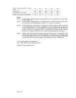
Gas pressure to Gas Valve Unit, min
kPa (a)
1015
1015
1015
1015
Gas temperature before Gas Valve Unit
°C
0...60
0...60
0...60
0...60
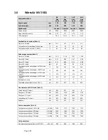
Lubricating oil system
Pressure before bearings, nom. (PT 201)
kPa
420
420
420
420
Suction ability, including pipe loss, max.
kPa
40
40
40
40
Priming pressure, nom. (PT 201)
kPa
150
150
150
150
Suction ability priming pump, including pipe
loss, max.
kPa
35
35
35
35
Temperature before bearings, nom. (TE 201)
°C
70
70
70
70
Temperature after engine, approx.
°C
82
82
82
82
Pump capacity (main), engine driven
m
3
/h
125
130
125
130
Pump capacity (main), electrically driven
m
3
/h
100
100
100
100
Priming pump capacity (50/60Hz)
m
3
/h
40.0 /
40.0
40.0 /
40.0
40.0 /
40.0
40.0 /
40.0
Oil volume, wet sump, nom.
m
3
2.8
2.8
2.8
2.8
Oil volume in separate system oil tank
m
3
5
5
5
5
Oil consumption at 100% load, approx.
g/kWh
0.35
0.35
0.35
0.35
Crankcase ventilation flow rate at full load
l/min
1960
1960
1960
1960
Crankcase ventilation backpressure, max.
kPa
0.1
0.1
0.1
0.1
Oil volume in turning device
l
9.0...11.0
9.0...11.0
9.0...11.0
9.0...11.0
Cooling water system
HT cooling water system
Pressure at engine, after pump, nom. (PT 401)
kPa
358 +
static
358 +
static
358 +
static
358 +
static
Pressure at engine, after pump, max. (PT 401)
kPa
600
600
600
600
Temperature before cylinders, approx. (TE 401)
°C
83
83
83
83
Temperature after engine, nom.
°C
96
96
96
96
Capacity of engine driven pump, nom.
m
3
/h
80
80
80
80
Pressure drop over engine, total
kPa
210
210
210
210
Pressure drop in external system, max.
kPa
100
100
100
100
Pressure from expansion tank
kPa
70...150
70...150
70...150
70...150
Water volume in engine
m
3
0.35
0.35
0.35
0.35
Delivery head of stand-by pump
kPa
365
365
365
365
LT cooling water system
Pressure at engine, after pump, nom. (PT 451)
kPa
650+
static
650+
static
650+
static
650+
static
Temperature before engine, nom (TE 451)
°C
40/ 45
40/ 45
40/ 45
40/ 45
Capacity of engine driven pump, nom.
m
3
/h
80
80
80
80
Pressure drop over charge air cooler (two-stage)
kPa
110
110
110
110
Pressure drop in external system, max.
kPa
100
100
100
100
Pressure from expansion tank
kPa
70...150
70...150
70...150
70...150
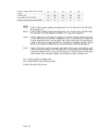
Starting air system
Pressure, nom.
kPa
3000
3000
3000
3000
Summary of Contents for 31SG
Page 1: ...Page 1 PRODUCT GUIDE W rtsil 31SG...
Page 4: ...Page 4 This page intentionally left blank...
Page 8: ...Page 8 This page intentionally left blank...
Page 14: ...Page 14 This page intentionally left blank...
Page 21: ...Page 21 This page intentionally left blank...
Page 43: ...Page 43 This page intentionally left blank...
Page 49: ...Page 49 Fig 5 1 Flexible hoses...
Page 52: ...Page 52 This page intentionally left blank...
Page 58: ...Page 58 Fig 6 4 Gas valve unit reference P I diagram DAAF051037D...
Page 60: ...Page 60 Fig 6 7 Gas valve unit P I diagram open type DAAF085795A...
Page 64: ...Page 64 Fig 7 2 Lubricating oil system single engine wet sump DAAF301501B...
Page 65: ...Page 65 Fig 7 3 Lubricating oil system Gas multiple engines wet sump DAAF301500A...
Page 72: ...Page 72 This page intentionally left blank...
Page 77: ...Page 77 Fig 9 1 Example diagram for multiple main engines DAAF301505A...
Page 87: ...Page 87 This page intentionally left blank...
Page 98: ...Page 98...
Page 109: ...Page 109 This page intentionally left blank...
Page 113: ...Page 113 This page intentionally left blank...
Page 119: ...Page 119 This page intentionally left blank...
Page 122: ...Page 122 18 4 1 Service space requirement 18 4 1 1 Service space requirement engine...
Page 124: ...Page 124 This page intentionally left blank...
Page 127: ...Page 127 This page intentionally left blank...
Page 129: ...Page 129 This page intentionally left blank...
Page 132: ...W rtsil 31SG Product Guide Page 132 21 2 Collection of drawing symbols used in drawings...


