Page | 73
8.
Compressed Air System
Compressed air is used to start engines and to provide actuating energy for safety and control
devices. The use of starting air for other purposes is limited by the classification regulations.
To ensure the functionality of the components in the compressed air system, the compressed
air has to be free from solid particles and oil.
8.1
Instrument air quality
The quality of instrument air, from the ships instrument air system, for safety and control devices
must fulfill the following requirements.
Instrument air specification:
Design pressure
1 MPa (10 bar)
Nominal pressure
0.7 MPa (7 bar)
Dew point temperature
+3°C
Max. oil content
1 mg/m
3
Max. particle size
3 µm
8.2
External compressed air system
The design of the starting air system is partly determined by classification regulations. Most
classification societies require that the total capacity is divided into two equally sized starting air
receivers and starting air compressors. The requirements concerning multiple engine
installations can be subject to special consideration by the classification society.
The starting air pipes should always be slightly inclined and equipped with manual or automatic
draining at the lowest points.
Instrument air to safety and control devices must be treated in an air dryer.
Summary of Contents for 31SG
Page 1: ...Page 1 PRODUCT GUIDE W rtsil 31SG...
Page 4: ...Page 4 This page intentionally left blank...
Page 8: ...Page 8 This page intentionally left blank...
Page 14: ...Page 14 This page intentionally left blank...
Page 21: ...Page 21 This page intentionally left blank...
Page 43: ...Page 43 This page intentionally left blank...
Page 49: ...Page 49 Fig 5 1 Flexible hoses...
Page 52: ...Page 52 This page intentionally left blank...
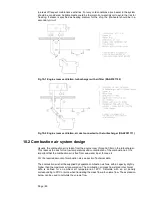
Page 58: ...Page 58 Fig 6 4 Gas valve unit reference P I diagram DAAF051037D...
Page 60: ...Page 60 Fig 6 7 Gas valve unit P I diagram open type DAAF085795A...
Page 64: ...Page 64 Fig 7 2 Lubricating oil system single engine wet sump DAAF301501B...
Page 65: ...Page 65 Fig 7 3 Lubricating oil system Gas multiple engines wet sump DAAF301500A...
Page 72: ...Page 72 This page intentionally left blank...
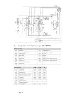
Page 77: ...Page 77 Fig 9 1 Example diagram for multiple main engines DAAF301505A...
Page 87: ...Page 87 This page intentionally left blank...
Page 98: ...Page 98...
Page 109: ...Page 109 This page intentionally left blank...
Page 113: ...Page 113 This page intentionally left blank...
Page 119: ...Page 119 This page intentionally left blank...
Page 122: ...Page 122 18 4 1 Service space requirement 18 4 1 1 Service space requirement engine...
Page 124: ...Page 124 This page intentionally left blank...
Page 127: ...Page 127 This page intentionally left blank...
Page 129: ...Page 129 This page intentionally left blank...
Page 132: ...W rtsil 31SG Product Guide Page 132 21 2 Collection of drawing symbols used in drawings...

