Page | 86
where:
qc = combustion air volume flow [m³/s]
m' = combustion air mass flow [kg/s]
ρ
= air density 1.15 kg/m³
The fans should preferably have two-speed electric motors (or variable speed) for enhanced
flexibility. In addition to manual control, the fan speed can be controlled by engine load.
In multi-engine installations each main engine should preferably have its own combustion air
fan. Thus the air flow can be adapted to the number of engines in operation.
The combustion air should be delivered through a dedicated duct close to the turbocharger,
directed towards the turbocharger air intake. The outlet of the duct should be equipped with
a flap for controlling the direction and amount of air. Also other combustion air consumers, for
example other engines, gas turbines and boilers shall be served by dedicated combustion
air ducts.
If necessary, the combustion air duct can be connected directly to the turbocharger with a
flexible connection piece. With this arrangement an external filter must be installed in the duct
to protect the turbocharger and prevent fouling of the charge air cooler. The permissible total
pressure drop in the duct is max. 1.5 kPa. The duct should be provided with a step-less
change-over flap to take the air from the engine room or from outside depending on engine
load and air temperature.
For very cold conditions arctic setup is to be used. The combustion air fan is stopped during
start of the engine and the necessary combustion air is drawn from the engine room. After
start either the ventilation air supply, or the combustion air supply, or both in combination
must be able to maintain the minimum required combustion air temperature. The air supply
from the combustion air fan is to be directed away from the engine, when the intake air is cold,
so that the air is allowed to heat up in the engine room.
10.2.1 Charge air shut-off valve (optional)
In installations where it is possible that the combustion air includes combustible gas or vapour
the engines can be equipped with charge air shut-off valve. This is regulated mandatory where
ingestion of flammable gas or fume is possible.
10.2.2 Condensation in charge air coolers
Air humidity may condense in the charge air cooler, especially in tropical conditions. The
engine is equipped with an active dewpoint control to minimize condensation in the charge
air coolers and -receiver, by raising the LT-cooling water temperature based on ambient
humidity and charge air pressure. The engine is also equipped with a small drain pipe from
the charge air cooler and receiver for possible condensed water. Humidity sensor is mounted
in external system.
Summary of Contents for 31SG
Page 1: ...Page 1 PRODUCT GUIDE W rtsil 31SG...
Page 4: ...Page 4 This page intentionally left blank...
Page 8: ...Page 8 This page intentionally left blank...
Page 14: ...Page 14 This page intentionally left blank...
Page 21: ...Page 21 This page intentionally left blank...
Page 43: ...Page 43 This page intentionally left blank...
Page 49: ...Page 49 Fig 5 1 Flexible hoses...
Page 52: ...Page 52 This page intentionally left blank...
Page 58: ...Page 58 Fig 6 4 Gas valve unit reference P I diagram DAAF051037D...
Page 60: ...Page 60 Fig 6 7 Gas valve unit P I diagram open type DAAF085795A...
Page 64: ...Page 64 Fig 7 2 Lubricating oil system single engine wet sump DAAF301501B...
Page 65: ...Page 65 Fig 7 3 Lubricating oil system Gas multiple engines wet sump DAAF301500A...
Page 72: ...Page 72 This page intentionally left blank...
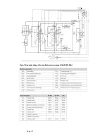
Page 77: ...Page 77 Fig 9 1 Example diagram for multiple main engines DAAF301505A...
Page 87: ...Page 87 This page intentionally left blank...
Page 98: ...Page 98...
Page 109: ...Page 109 This page intentionally left blank...
Page 113: ...Page 113 This page intentionally left blank...
Page 119: ...Page 119 This page intentionally left blank...
Page 122: ...Page 122 18 4 1 Service space requirement 18 4 1 1 Service space requirement engine...
Page 124: ...Page 124 This page intentionally left blank...
Page 127: ...Page 127 This page intentionally left blank...
Page 129: ...Page 129 This page intentionally left blank...
Page 132: ...W rtsil 31SG Product Guide Page 132 21 2 Collection of drawing symbols used in drawings...


