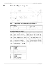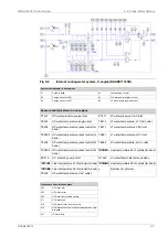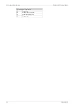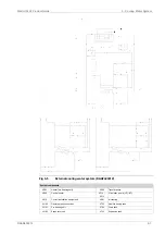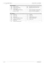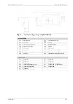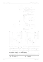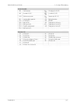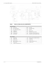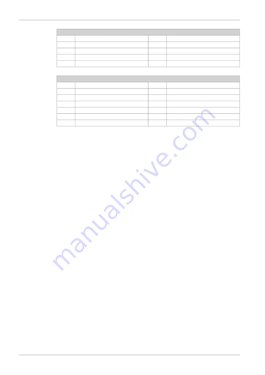
System components
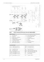
Temperature control valve (heat recovery)
4V02
Stand-by pump (HT)
4P03
Temperature control valve (central cooler)
4V08
Circulation pump (preheater)
4P04
Stand-by pump (LT)
4P05
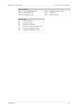
Install at the highest point in the piping system
**
In case of turbocharger at driving end
*
Alternative location with oversized pump
****
In case of W14V46DF
***
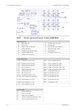
Pipe connections
LT-water inlet
451
HT-water inlet
401
LT-water outlet
452
HT-water outlet
402
LT-water air vent from air cooler
454
HT-water air vent
404
LT-water from stand-by pump
457
HT- water from preheater to HT-circuit
406
LT-water air vent
483
HT-water from stand-by pump
408
HT-water drain
411
HT-water air vent from air cooler
416
9-8
DAAB605814
Wärtsilä 46F Product Guide
9. Cooling Water System
Summary of Contents for 46F Series
Page 1: ...Wärtsilä 46F PRODUCT GUIDE ...
Page 4: ...This page intentionally left blank ...
Page 8: ...This page intentionally left blank ...
Page 18: ...This page intentionally left blank ...
Page 86: ...This page intentionally left blank ...
Page 104: ...This page intentionally left blank ...
Page 154: ...This page intentionally left blank ...
Page 162: ...This page intentionally left blank ...
Page 170: ...This page intentionally left blank ...
Page 176: ...This page intentionally left blank ...
Page 194: ...This page intentionally left blank ...
Page 200: ...This page intentionally left blank ...
Page 202: ...This page intentionally left blank ...
Page 207: ...Fig 21 7 List of symbols DAAF406507 7 DAAB605814 21 5 21 ANNEX Wärtsilä 46F Product Guide ...

