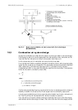
a flap for controlling the direction and amount of air. Also other combustion air consumers,
for example other engines, gas turbines and boilers shall be served by dedicated combustion
air ducts.
If necessary, the combustion air duct can be connected directly to the turbocharger with a
flexible connection piece. With this arrangement an external filter must be installed in the duct
to protect the turbocharger and prevent fouling of the charge air cooler. The permissible total
pressure drop in the duct is max. 1.5 kPa. The duct should be provided with a step-less
change-over flap to take the air from the engine room or from outside depending on engine
load and air temperature.
For very cold conditions arctic setup is to be used. The combustion air fan is stopped during
start of the engine and the necessary combustion air is drawn from the engine room. After
start either the ventilation air supply, or the combustion air supply, or both in combination
must be able to maintain the minimum required combustion air temperature. The air supply
from the combustion air fan is to be directed away from the engine, when the intake air is cold,
so that the air is allowed to heat up in the engine room.
10.2.1
Condensation in charge air coolers
Air humidity may condense in the charge air cooler, especially in tropical conditions. The
engine equipped with a small drain pipe from the charge air cooler for condensed water.
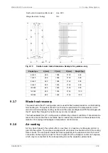
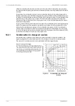
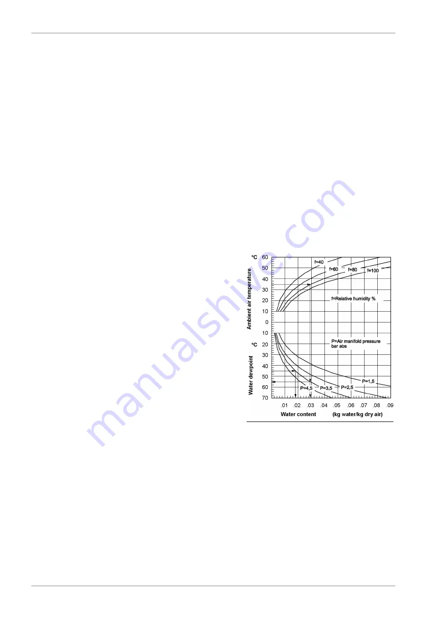
The amount of condensed water can be estimated with the diagram below.
Fig 10-3
Condensation in charge air
coolers
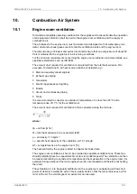
Example, according to the diagram:
At an ambient air temperature of 35°C and a relative humidity of
80%, the content of water in the air is 0.029 kg water/ kg dry air.
If the air manifold pressure (receiver pressure) under these condi-
tions is 2.5 bar (= 3.5 bar absolute), the dew point will be 55°C.
If the air temperature in the air manifold is only 45°C, the air can
only contain 0.018 kg/kg. The difference, 0.011 kg/kg (0.029 -
0.018) will appear as condensed water.
10-4
DAAB605814
Wärtsilä 46F Product Guide
10. Combustion Air System
Summary of Contents for 46F Series
Page 1: ...Wärtsilä 46F PRODUCT GUIDE ...
Page 4: ...This page intentionally left blank ...
Page 8: ...This page intentionally left blank ...
Page 18: ...This page intentionally left blank ...
Page 86: ...This page intentionally left blank ...
Page 104: ...This page intentionally left blank ...
Page 154: ...This page intentionally left blank ...
Page 162: ...This page intentionally left blank ...
Page 170: ...This page intentionally left blank ...
Page 176: ...This page intentionally left blank ...
Page 194: ...This page intentionally left blank ...
Page 200: ...This page intentionally left blank ...
Page 202: ...This page intentionally left blank ...
Page 207: ...Fig 21 7 List of symbols DAAF406507 7 DAAB605814 21 5 21 ANNEX Wärtsilä 46F Product Guide ...

