background image


JOVYATLAS POWERMASTER S 6000-P       BAX 4469 E                                                     

  -  21 -


S E R V I C E – H O T L I N E ! 


Telephone: +49 4958 - 9394 - 30     Telefax: +49 4958 - 9394 - 10 

E-Mail: 

service@jovyatlas.de


Internet: 

http://www.jovyatlas.de


Service-Information 


10 

Remote monitoring 

 
The UPS unit is fitted as standard with an RS 232 signal output. This signal output is designed as a RS232-
interface  (SUB-D,  9-pin),  and  there  is  optionally  the  possibility  of  using  an  additional  USB  interface. 
Concerning these two interfaces there is the limitation that only one or the other, that is the RS232 or the 
USB interface, can be used only one at a time. There is also the option of using the additional rack at the 
rear. This rack can be fitted with two different cards, one with an SNMP adapter, which allows monitoring of 
the UPS via the network or the internet, or an AS/400 card with voltage-free contacts. 


The RS 232 and USB interfaces serve to allow data transmission between a computer and the UPS unit. 


The UPS unit can be monitored and checked by a computer through the use of special software. Switching 
off of the UPS unit in the case of power failure is possible. 


10.1 

Connecting the UPS to the computer 


The  communication  between  the  UPS  and  computer  is  delivered  as  a  complete  package  including  the 
communication cable and management software. It is absolutely essential to use the communication cable 
delivered  since  it  was  directly  configured  for  the  RS  232  interface.  Ensure  that  your  operating  system  is 
compatible with the management software. Instructions for the management software will aid you in installing 
the software properly.  


10.2 

Assignment of the RS232 interface 

 
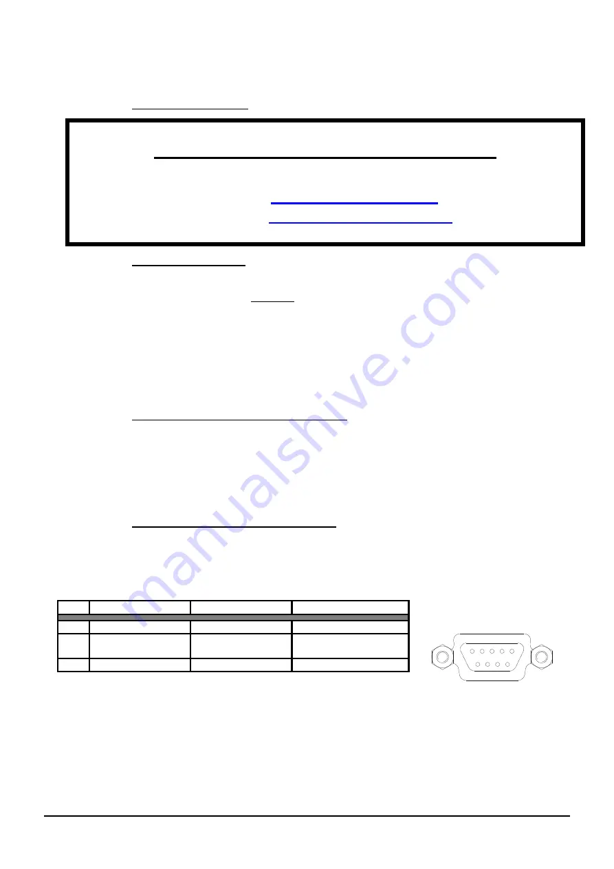
The  RS  232  interface  uses  a  9-pin  SUB-D  connector  (jack).  Assignment  of  the  SUB-D  connector  is  as 
described in the table below. 


Pin assignment for the RS 232 interface                                                                


 RS 232 interface 


(Rear side of UPS) 

PIN   SIGNAL 

DIRECTION 

FUNCTION 


TxD 

Output 

TxD output 

RxD 

Input 

RxD/inverter out  
Input 

GND 


GND 


Graphic 14: RS232 interface 


1

2

3

4

5

6

7

8

9

Summary of Contents for JOVYATLAS POWERMASTER S 6000

Page 1: ...JOVYATLAS POWERMASTER S 6000 P BAX 4469 E 1 Operating Manual UPS System POWERMASTER S 6000 P BAX 4469E...

Page 2: ...R S 6000 P BAX 4469 E 2 Index Date Name Remarks 0 2012 04 23 Chr Fechteler Original 1 2014 06 13 Chr Fechteler 14 349 2 2014 11 06 Chr Fechteler 14 608 3 2015 07 22 Chr Fechteler 15 381 4 2015 09 25 C...

Page 3: ...source of information W RTSIL JOVYATLAS EUROATLAS GmbH reserves the right to make any necessary changes to the contents and technology described in this operating manual without having to make an anno...

Page 4: ...7 2 SHUTTING DOWN THE SINGLE UPS 15 7 3 COMMISSIONING THE UPS IN PARALLEL OPERATION 16 7 4 SHUTTING DOWN THE UPS IN PARALLEL OPERATION 16 8 OPERATION AND DISPLAYPANEL 17 8 1 PANEL 17 8 2 PARAMETER OF...

Page 5: ...4 weeks after receipt in order to prevent the battery discharging itself 1 General Notes The device may only be opened by trained specialists The system is to be connected up and earthed according to...

Page 6: ...tion During normal operation the battery and the inverter are supplied with power via a rectifier online operation The change over from alternating voltage to direct voltage and back to alternating vo...

Page 7: ...pass operation In the case of a fault occurring in the inverter or an overload a switch over device switches the load back to the mains This means that in the case of a power failure the connected con...

Page 8: ...ure 0 ms Overload switching Automatic overload switching by the UPS unit Noise level At an approx distance of 1 metre 55dB A Environment Temperature 0 C to 40 C 15 25 C recommended Air humidity 0 to 9...

Page 9: ...BAX 4469 E 9 5 Views of JOVYATLAS Powermaster S 6000 P 5 1 Front and Rear View Figure 4 Front View Figure 5 Rear View and Terminal Block FAN COVER Panel Mounting Angles FAULT BYPASS ON BAT ON LINE ON...

Page 10: ...RPACK S 6000 1 Figure 6 Front View POWERPACK S 6000 3 2 Figure 7 Rear View POWERPACK S 6000 4 Position Designation 1 Cover Plate left and right removable 2 Mounting and Retaining Bracket for 19 mounti...

Page 11: ...outs 5 Connect the input cable to the terminals with the designation input L N PE 6 Connect the output cable to the terminals with the designation output L N PE 7 Fix the cover plate with a Phillips s...

Page 12: ...cted in between the feeding mains and the UPS Figure 8 Using Reverse Voltage Protection If the reverse voltage protection is not used please connect the inputs like shown in picture below Figure 9 Wit...

Page 13: ...Anlagen wird ein Kabel von USV 1 nach USV 2 sowie ein Kabel von USV 2 nach USV 3 geschaltet Es darf keine Ringverbindung geschaffen werden Figure 10 Connection of external Battery Packs 6 4 Connection...

Page 14: ...JOVYATLAS POWERMASTER S 6000 P BAX 4469 E 14 Figure 11 Connection of a Parallel System UPS UPS UPS UPS Load MAINS...

Page 15: ...ting down the single UPS 1 Push Button MENU ENTER to choose Menu UPS Command 2 Push Button MENU ENTER to choose Menu Start UPS ON OFF 3 Push Button MENU ENTER to choose Menu UPS runs to Bypass 4 Open...

Page 16: ...Please check if all BYPASS LED s are not lighting all ON LINE LED are lighting the display will show message Line Mode Parallel Important Notice Prior to connecting the load to the output of the syste...

Page 17: ...l flash in yellow when input voltage magnitude or frequency is out of tolerance ON LINE This LED will light up in green when the UPS is operating on line mode ON BAT This LED will light up in red when...

Page 18: ...LD START LANGUAGE FAULT REC TIME CLEAR FAULT REC LCD VERSION CORE VERSION UPS SERIAL No DISABLE ENABLE Line config Disable 208 220 230 240V BATT TEST TIME BATT TEST PERIOD AUTO MANUAL TEST 1 2 3 DISAB...

Page 19: ...S O P FREQ 50 0Hz Output Frequency of UPS BAT VOLT 276V Battery Voltage of Battery Pack O P LOAD 80 Load in Percent O P CURR 13A Load Current in Ampere O P W 2300W Load in Watt O P VA 3000VA Load in V...

Page 20: ...al Failure check the PFC Rectifier Inverter fault Internal Failure check the Inverter Over temperature Check Function of the Fan or if something is blocking the Air Outlet Batt over volt Internal Fail...

Page 21: ...llow data transmission between a computer and the UPS unit The UPS unit can be monitored and checked by a computer through the use of special software Switching off of the UPS unit in the case of powe...

Page 22: ...tion of the external electronic STOP switch causes the output of the UPS unit to be switched to voltage free and the UPS unit shuts down In order to provide the consumers with a voltage again the elec...

Page 23: ...e UPS unit to be switched voltage free and the UPS unit shuts down In order to supply consumers with voltage again it is necessary for the electronic STOP switch to be reset and for the UPS to be rest...

Page 24: ...JOVYATLAS POWERMASTER S 6000 P BAX 4469 E 24 14 Circuit diagram relay board...

Page 25: ...attery At the end of the bridging time the inverter switches off automatically and the consumers are no longer supplied with power When the mains power is restored the consumers begin again to be supp...

Page 26: ...UPS has to be recharged in case of UPS is being switched off totally after latest four weeks It is sufficient to connect the UPS to an input mains The recharging time shall be at least 8 hours We reco...

Reviews: