Wärtsilä JOVYSTAR
– DELTA 40 – 150kVA BAX 4647E - 30 -
5.2.2
System Layouts
The parallel redundant system has better static and dynamic performances in comparison to a single unit since, owing
to the redundancy, the total amount of power available his higher than the nominal load of the overall system.
Overload
The overload limit of a parallel redundant system depends on the number of the units which are connected to the load:
Imax = n x In, where “n” = number of the units, “In” = nominal current of each unit.
If the load exceeds this limit the thermal image protection is activated and, after a certain time the load is transferred to
bypass (if available).
Short circuit
In case of a short circuit at system output the load is transferred to bypass (if it is available).
5.2.3
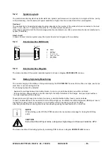
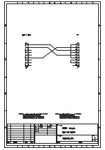
Interconnection BUS Cable
5.2.4
Interconnection Diagram
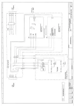
The interconnection of the parallel-redundant system is shown in diagram
X0012900.VP3
in annex.
5.3
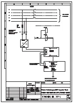
Battery Symmetry Monitoring
The correct charging of the battery is being monitored by the PCB
P0037401
In case of more than one ropes, each rope
must have is own monitoring-module.
The following faults will be detected:
- Asymmetrical voltage between the battery blocks in a row (e.g. a defective battery cell within one block)
- In case of using voltage sensors connected directly to the output terminals of the charger, am open line as well as a
too high impedance will be detected.
These problems might arise as a matter of corrosive contacts defective battery fuses or weak contacts.
In case of a detect
ed fault, the red LED V9 on the PCB will light up. In addition the UPS will signalize „BCB open“ due to
the fact that a relay contact is connected in a row together with the monitoring contact of the BCB.
After fixing the fault the monitoring circuit has to be reset by pushing the reset button S1 on the PCB.
i
NOTE:
When starting up the UPS this PCB has also to be reset when a message for closing the BCB ap-
pears.
CAUTION:
Even at switched off input mains, a dangerous high voltage is still present inside the UPS!
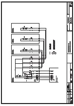
The interconnection of the battery symmetry monitoring PCB is shown in diagram
X0037401.AS3
in annex.
9
6
1
5
5
9
1
6
DB 9 MALE
DB 9 MALE
PIN
SIGNAL
2
3
4
5
7
9
BUSCAN_L
BUS_GND
INT_SYNC_BUS
MAINS_SYNC_BUS
BUS_CANH
BUS_POWER


