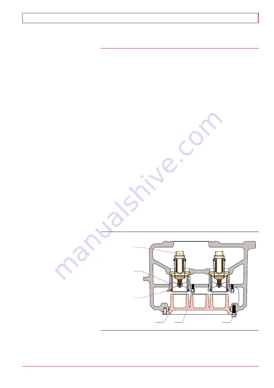
19.4.3 HT thermostatic valve
The HT thermostatic valve is integrated in the pump cover at the
free end of the engine. It is equipped with positive three-way valve
action in which the water is positively made to flow in the direction
required. When the engine is started up and is cold, the HT
thermostatic valve causes all of the water to be positively by-
passed back into the pump, thus providing the quickest warm-up
period possible. After warm up, the correct amount of water is
by-passed and automatically mixed with the cold water returning
from the heat exchanger or other cooling device to produce the
desired HT water outlet temperature. If ever required, the HT
thermostatic valve will shut off positively on the by-pass line for
maximum cooling. The three-way action of the valve allows a
constant water flow through the pump and engine at all times
with no pump restriction when the engine is cold.
No adjustments are ever required on the HT thermostatic valve.
The temperature is permanently set at the factory. The tempera-
ture can be changed only by changing temperature element
assemblies which is easily accomplished by unscrewing the cover.
The HT valve is entirely self-contained, and there are no external
bulbs or lines to become damaged or broken. There are no packing
glands to tighten and no parts to oil.
The power creating medium utilizes the expansion of the ele-
ment contents (2), Fig 19-7, which remains in a semi-solid form
and is highly sensitive to temperature changes. Most of the
expansion takes place during the melting period of approximately
two minutes over a temperature change of approximately 8.5°C.
HT thermostatic valve
1. Screw
2. Screw
5
6
4
3
1
2
3. Cover
4. O-ring
5. Element holder
6. Thermostat element
Fig 19-7
4019049601
32-200050
Cooling Water System
19
WÄRTSILÄ 32
19 - 11
Summary of Contents for PAAE051728
Page 4: ......
Page 18: ...Appendix B Welding Precautions 200640 00 6...
Page 26: ...01 Main Data Operating Data and General Design 32 200634 01 01 8 W RTSIL 32...
Page 60: ...Appendix A Environmental Hazards 200507 02A 10...
Page 68: ...Page 7 7 Document No 4V92A0645 Rev j...
Page 84: ...03 Start Stop and Operation 32 200402 04 03 12 W RTSIL 32...
Page 98: ...04 Maintenance Schedule 32 200623 01 04 14 W RTSIL 32...
Page 154: ...07 Tightening Torques and Use of Hydraulic Tools 32 200643 01 07 30 W RTSIL 32...
Page 162: ...08 Operating Troubles Emergency Operation 32 200402 01 08 8 W RTSIL 32...
Page 164: ...Specific Installation Data 2005 01 09 2...
Page 178: ...10 Engine Block with Bearings Oil Sump and Cylinder Liner 32 200150 10 14 W RTSIL 32 34SG...
Page 216: ...Appendix A Testing of cylinder tightness 32 200142 A 4 W rtsil 20 32 34...
Page 226: ...13 Camshaft Driving Gear 32 200546 02 13 10 W RTSIL 32...
Page 254: ...15 Turbocharging and Air Cooling 32 200549 10 15 20 W RTSIL 32...
Page 274: ...16 Injection System 32 200627 01 16 20 W RTSIL 32...
Page 280: ...Fuel System 32 200508 07 17 6 W RTSIL 32...
Page 314: ...19 Cooling Water System 32 200050 19 14 W RTSIL 32...
Page 394: ...23 Instrumentation and Automation 32 200115 II 23 60 W RTSIL 32...


