7.3.2
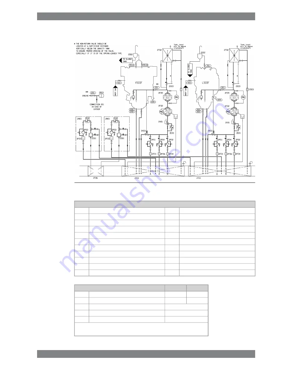
External LO system without engine driven pumps
Fig 7-4
Example of lubricating oil system, without engine driven pumps
(DAAF001973A)
System components:
Separator pump (separator unit)
2P03
Lubricating oil cooler
2E01
Stand-by pump
2P04
Heater (separator unit)
2E02
Lubricating oil damper
2R03
Suction strainer (main lubricating oil pump)
2F01
Separator
2S01
Automatic filter
2F02
Condensate trap
2S02
Suction filter (separator unit)
2F03
Sight glass
2S03
Suction strainer (pre lubricating oil pump)
2F04
System oil tank
2T01
Safety filter (LO)
2F05
Gravity tank
2T02
Suction strainer (stand-by pump)
2F06
Sludge tank
2T06
Separator unit
2N01
Temperature control valve
2V01
Main lubricating oil pump
2P01
Pressure control valve
2V03
Pre lubricating oil pump
2P02
V50DF
L50DF
Pipe connections:
DN125
Lubricating oil inlet
201
DN200
Lubricating oil outlet
1)
202
M18*1.5
Control oil to lube oil pressure control valve
224
OD114
Crankcase air vent
701
DN50
Inert gas inlet
723
1) Two outlets in each end are available, outlets to be used:
6L, 12V: FE 1, DE 1
8L, 9L, 16V, 18V: FE 1, DE 2
Wärtsilä 50DF Product Guide - a16 - 9 September 2016
7-7
7. Lubricating Oil System
Wärtsilä 50DF Product Guide
Summary of Contents for WARTSILA 50DF
Page 1: ...WÄRTSILÄ 50DF PRODUCT GUIDE ...
Page 14: ...This page intentionally left blank ...
Page 40: ...This page intentionally left blank ...
Page 58: ...This page intentionally left blank ...
Page 102: ...This page intentionally left blank ...
Page 120: ...This page intentionally left blank ...
Page 154: ...This page intentionally left blank ...
Page 164: ...This page intentionally left blank ...
Page 176: ...This page intentionally left blank ...
Page 214: ...This page intentionally left blank ...
Page 232: ...This page intentionally left blank ...
Page 234: ...This page intentionally left blank ...
Page 237: ......
Page 238: ......
Page 239: ......


