1.3 Safety instructions
1.4 Components and spares
1.5 Accuracy of measurements
1.6 Dismantling instructions
General
Please read the safety instructions on the rear panel before opening the device. Above all, be
sure to disconnect the device from the mains before commencing any repair work. Special
care must be taken when working in the power amplifier areas as DC voltages in excess of
>140V (power amplifier) may be present. The normal precautions should be observed when
working with MOS elements
Any parts that prove defective should only be replaced by original spare parts as the use of
substitute types could result in a shifting of the operating point, with the result that the correct
operation of the device can no longer be guaranteed. This is especially true in the area of the
power amplifier where components have been precisely measured
To remove the front panel, first loosen the
screws highlighted in black.
Then remove the power supply cable and
accompanying cable fasteners from
inside the device.
In order to dismantle the power amplifier,
loosen the screws marked in grey in Fig.
2. Then the cables that are plugged in
should be removed before the soldered
cables are separated from their contacts.
The measurements documented in the circuit specifications are to be understood as
approximate values. Any deviation from the stated values should not, however, exceed 10%.
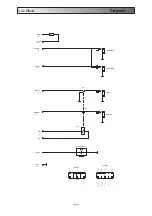
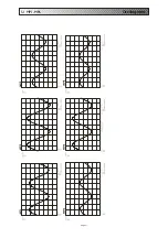
The oscillograms for themeasurement points (exceptMP7)beginatpage17.
Front Panel
Power Amplifier
Fig. 2.: Position of the srews
a) front panel; b) base; c) rear panel
a)
b)
c)
Page 4


