background image

2.3

Short-circuit protection

Power amp / Protections

Testing/Regulating

When the device is switched on, there should be a noticeable delay before it powers up.
You should be able to hear the relay operating. The length of the delay should be about
two seconds.

The following procedure is used to test the circuit that protects against DC voltage at the
output:

Switch off the device
Removed fuses

to

(

)

Connect a multimeter to the emitter of transistor T17 (

)

Connect a stabilised DC source (

) to the output

Switch on the

Now slowly raise the DC voltage at the

's output (positive and negative tests) until

the device is seen to switch off (the Mute LED will illuminate and the relay will switch off).
When the switch-off occurs, the voltage at T17 should be c. 0.6V.
If the

has not switched off by the time the DC source voltage reaches 3V, there is a

fault.
Note that there is an electrolytic capacitor in the protective circuit to ensure a sluggish
response. That is why it is essential to increase the voltage slowly. The external DC voltage is
interrupted when the relay switches off and after a short interval, during which the power
amplifier will be in Standbymode,itwillreturntoOperatingmode

Before performing this test, the stabilised DC voltage power supply should be set to +8V.
The simplest way of connecting the Earth is to connect it
to the

(Minus). The other output of the

voltage source is connected to NTC2. (

)

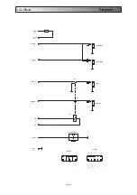
When testing the short-circuit protection, a 4ohm (250W) load
resistance is attached to the

of the amplifier and an

additional 1 (250 W) ohm load resistance to the earth of the
output (see Fig. 4) A sine wave signal of c. 1kHz should be
applied to the

and increased until the

oscilloscope at the output shows

DC Voltage Protection

Temperature control

Si1

Si2

ProFetII

Pro Fet IV

Pro Fet II

Speaker Out

Speaker Out

Effects Return

take care to discharge the input capacitors

1V range

set to 0V

Attention: one

pin of NTC 2 is connected to Earth

.

The following table shows how the protective circuit
reacts at various operating points.
Here too it should be borne in mind that the stated
voltage values are approximations and a variation of +
or - 10% is permissible.

Page 6

Fan ON

Standby ON

Standby OFF

Fan OFF

6V

7,5V

3,5V

4,5V

Fig. 4.: Short-circuit test

(SPEAKER OUT)

TTENTION:

If it becomes neccesary to replace a broken power amp transistor, it´s strongly

recommendet to use original spare parts supplied by the maufacturer only. Also,
even in case of ONE broken power amp transistor, you should replace the whole
set, which means 2x

or 2x

IRFP9240

IRFP240.

Summary of Contents for Pro Fet II

Page 1: ...Warwick Service Manual Pro Fet II Pro Fet II Front Pro Fet II Rear Subject to alteration Germany HDB electronic Letzte nderung Last alteration 02 1999...

Page 2: ...ds 3 3 Safety Instructions 4 4 Components and spares 4 5 Accuracy of measurements 4 6 Dismantling instructions 4 1 Basic Configuration 2 Preamp 5 3 Power amp 6 f 1 Block diagram 9 2 Wiring diagram 10...

Page 3: ...ht 11 5 kg Variable transformer Oscilloscop Ton generator Multimeter Stabilised DC pwer supply 0V 10V Loadresistance 4 ohms 250W Frequency Filter Headhpone 200 Ohm stereo Direct Out 0 dBu 600 Ohm Dime...

Page 4: ...esultthatthecorrect operation of the device can no longer be guaranteed This is especially true in the area of the poweramplifierwherecomponentshavebeenpreciselymeasured To remove the front panel firs...

Page 5: ...agramforthepreamp To test the Gain and Limiter LED a sine wave signal of approximately 1kHz variable in its amplitude isappliedtotheinput The signal is measured using an oscilloscope at or of The inpu...

Page 6: ...tingmode Beforeperformingthistest thestabilisedDCvoltagepowersupplyshouldbeset to 8V Thesimplestwayof connectingtheEarthistoconnectit to the Minus The other output of the voltage source is connected t...

Page 7: ...utput The measurements should be taken at room temperature and as soon as possible afterswitchingonthedevice aswarmingofthepoweramplifiercouldcausedeviations 10 Pro Fet II Trimmingthequiescent current...

Page 8: ...A1kHzsignalshouldthen bedirectedtothe and the control adjusted so that an output signal of 28V peak to peak 10 Veff ismaintained The frequency of the input signal should be switched to 10Hz and then...

Page 9: ...3 1 Block diagram Diagrams Page 9...

Page 10: ...3 2 Wiring diagram Diagrams Page 10...

Page 11: ...0k 10k 10k 10k 10k 10k 10k 10k 18k2 NE5532 22k1 1M 2k21 22p 100k 22k1 22k1 2k21 2k21 22k1 TL074 TL074 TL074 MUTE 475 10k GND PHONE EFF RET EFF SEND LINE OUT TUNER OUT GND 24V 24V GND PA PA IN LED MUTE...

Page 12: ...iagrams Page 12 EFFECT SEND EFFECT RETURN EFF SEND EFF RET LINE OUT TUNER OUT LINE OUT TUNER OUT PHONE 221 Rel rel1 rel2 GROUND FREE 100n 1M X1 X1 X1 X1 X1 X1 GND X1 PHONE X2 REL REL X2 GND PCB Edge P...

Page 13: ...r amplifier Diagrams Page 13 4k75 4k75 4 7 10k 47k5 10k 100n 22k1 475k 22k1 22k1 10k 47k5 1k MUTE LED 24V 24V GND INPUT GND REL REL PHONE 4002 15k4 4k75 4002 0 22 0 22 0 22 0 22 121 121 1k 121 825 475...

Page 14: ...10k 10k 330n 10k 10k 2 2n 10k 10k 10k 1n 10k 10k 10k 2k21 1M 5k62 2 2M 100k 4148 TL074 3k32 3k32 4148 4148 4148 22k1 100k 10k 100k 100k 47 5 22k1 47 5 2k21 22k1 4148 2k21 1k 1k 2k21 100k 3k9k 2k21 2k...

Page 15: ...4 2 FET2BU Board Layout Page 15 1M 100n...

Page 16: ...TC10k IRFP9240 IRFP9240 NTC100k Cermet 4k75 47k5 22k1 8k25 475k 1k 22k1 1 Ohm 4 7 Ohm 0 22 Ohm 332 4002 22k1 100n 332 4002 10k 27k4 500 4093 1k 4002 4002 100n 100n 100n 0 22 Ohm 22k1 0 22 Ohm 0 22 Ohm...

Page 17: ...Page 17 5 1 MP1 MP6 Oscillograms...

Page 18: ...6 1 Frequency Filter Analyser Curves Page 18...

Reviews: