12
Installation manual
3.3
Siting
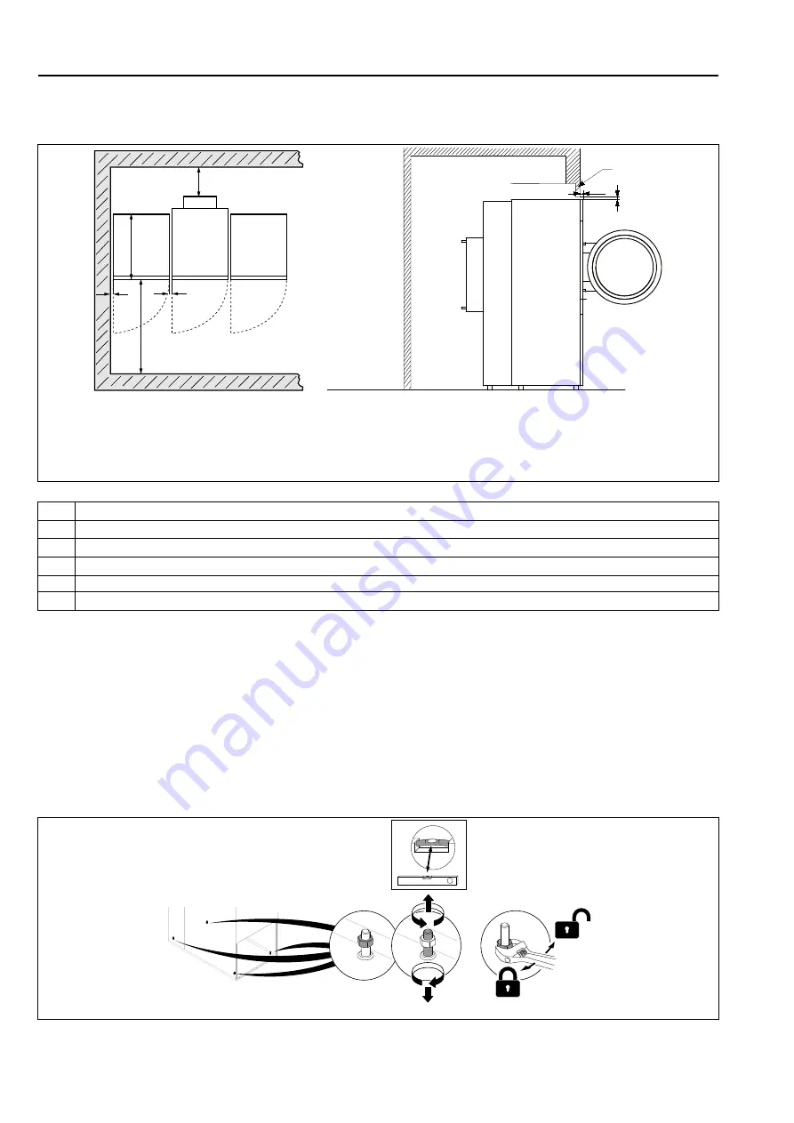
The figure shows recommended distance to walls and/or other machines.
B
C
A
A
D=C+B
E
F
1
2
Y
1= Top view
2 = Side view on built in machine
Y = For built-in machines it is recommended that the wall section Y is a removable finish piece. If so, E and F can be 0.
fig.X00959A
A
5–500 mm (Min. 5 mm)
B
500 mm (Min. 200 mm)
C
Depth of machine
D
D = C + B (Min. 1220 mm to be able to use the machine)
E
Min. 20 mm
F
Min. 25.4 mm (The overhead soffit may be used to close the gap above the machine. Min. required clearance: 0 mm)
Note!
The machine should be positioned so that there will be enough space for working, both for the user and
service personnel.
Respecting the given recommendations will provide easy access for maintenance and service operations.
In case of space limitations, it is possible to install machines without respecting to the given recommendations. If so,
keep in mind that it might be necessary to disconnect and move other machines to be able to reach and perform
service on affected machine.
3.4
Mechanical installation
Level the machine with the feet of the machine. The maximum height adjustment of the feet is 15 mm.
fig.X02472
Summary of Contents for D7-550
Page 1: ...Installation manual Tumble dryer D7 550 Type N2 Original instructions 438905413 EN 2023 02 27...
Page 2: ......
Page 4: ......
Page 42: ......
Page 43: ......


